Quick start
We’ve made a step-by-step tutorial to help you learn how to use the Antilatency tracking system and how to set up and configure your hardware.
Note, this tutorial only covers the most basic actions like software installation, tracking area assembly, and initial hardware setup. To learn more, please, read our HowTos. You can find links to some of them below.
As an example, let’s take a Floor tracking area of 10m², an Alt, and a Socket (Wired USB Socket or an Universal Radio Socket).
Install AntilatencyService
First, you need to install AntilatencyService. This utility allows you to choose the Environment scheme for your tracking area, set the Alt’s placement on the tracking object, and update the firmware or configure devices for special purposes.
We recommend using the latest version of the AntilatencyService app. You can download it here.
Choose the default Environment and Placement
Before using the Antilatency hardware, you need to choose the default Environment and Placement.
You need to set the default setting just once when first launching AntilatencyService.
In the Environments tab, you can configure the tracking area parameters and choose the default Environment. In this tutorial, we will use the floor area 2.4 x 2.4 m scheme, which you can find in the Environment examples for floor tracking areas.
You can find other examples for different tracking areas in this section.
In our case, you don't need to set Placement at all. But if you want to track a specific object, for example, an HMD, you need to set the exact location of the tracker on the tracking object. You can do this in the Placements tab.
Assemble the tracking area
Open the Environments tab in AntilatencyService, and then open the desired tracking area in the editor. In our case, this is the floor area 2.4 x 2.4 m scheme from the Environment examples.
Follow the instructions in this section to assemble and install tracking areas.
Configuring wireless devices
If your device kit contains wireless devices such as a Tag or a Bracer, you have to configure them before use.
For the quick setup of only two radio sockets follow these steps:
- connect an access point (Universal Radio Socket or Pico Native Socket) to the Host (VR headset or computer);
- make sure the both devices have the same LED indication a few seconds after turning them on:
| Indicator state | Device state |
|---|---|
Client is connected to an access point. The color should be identical on both devices. | |
This access point has at least one other client connected to it, the color will be identical on both devices. |
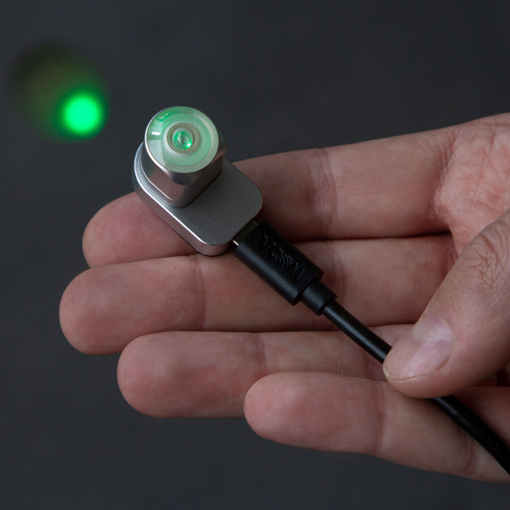
- place Alts in the radio devices.
The color of the LED indicator depends on the occupied radio channel. In total, there are 141 channels in the range of 2360-2500 MHz available for operation. For more information on radio channels and their use, see the Antilatency Radio Protocol.

Keep in mind this is just the basic setup and to really work with your project or for using more than two radio devices, you must fully configure them.
Run the Antilatency demo app
You can use the Antilatency demo app to test how our real-time tracking works. First, download the version of the application you need.
This demo application is built on Antilatency SDK version 4.1.0. Use AntilatencyService version 4.1.0 to work with the app.
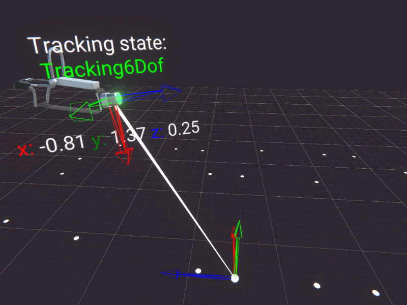
Connect the chosen Socket with the Alt to your device and launch the demo app. On the screen, you will see the position of the tracker. The current x, y, and z coordinates are shown under the representation of the tracker in the app.
Download Antilatency SDK
To use the Antilatency hardware, you need the Antilatency SDK. You can select the release and components, and then download a personal subset using our SDK Configurator.
The versions of the chosen SDK and AntilatencyService must match!
You can learn more about the latest updates in Releases.
Integration and interaction
You can add the Antilatency tracking system to various projects using these instructions:
- Antilatency SDK and game engines: Unity, Unreal Engine;
- integrations with Virtual Production programs;
- Antilatency tracking via FreeD;
- Antilatency tracking via VRPN;
- Antilatency and SteamVR.