Alt
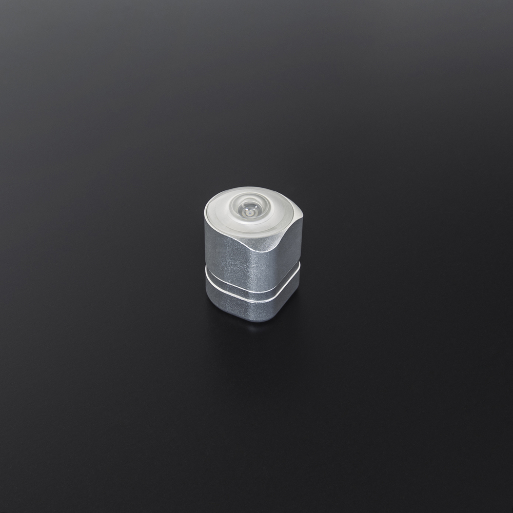
A tiny optical-inertial tracking module. The tracker is placed on objects that are being tracked. It determines their position in space.
In this article
- General information
The Alt is a small and lightweight 6DoF positional tracker. It can determine its position and orientation in space with submillimeter accuracy and low latency.
The Alt uses a sensor fusion approach for tracking: inertial measurement unit (IMU) provides inertial data with real-time IMU correction based on optical data.
Data correction takes place along the tracking area that consists of reference points — markers. A custom-designed lens with a 230-degree field of view can detect markers, even when the tracker is not pointed directly at them.
Sometimes the tracker fails to detect markers, for example, when the user accidentally obstructs the view of the optical sensor for a short time during the game. This doesn’t lead to a failure in operation — the system can continue tracking with inertial data alone.
The Alt can not only instantly obtain the current positioning data but also extrapolate it, i.e. predict the position of the tracked object in the future. This allows compensating for rendering latency.
Another way to reduce data processing latency is to free the Host (VR headset, PC, etc.) from some of the computation. For this purpose, the Alt provides onboard data processing. This allows to reduce the load on the communication channel and retain the performance of the host for other purposes.
Tracking real-world objects
The Alt can track any physical real-world objects: users’ body parts, furniture, camera.
You could place the Alt almost anywhere on the tracked object thanks to its small size. A Socket is required for tracker connectivity and fixation on the object. Each of the sockets extends the functionality and adapts the device for specific use cases (for example, a Bracer is convenient for hand tracking).
Use the Alt Bracket to secure the Alt in a socket connector. The Alt Bracket is a locking device designed to ensure a reliable connection between the Alt and a socket.
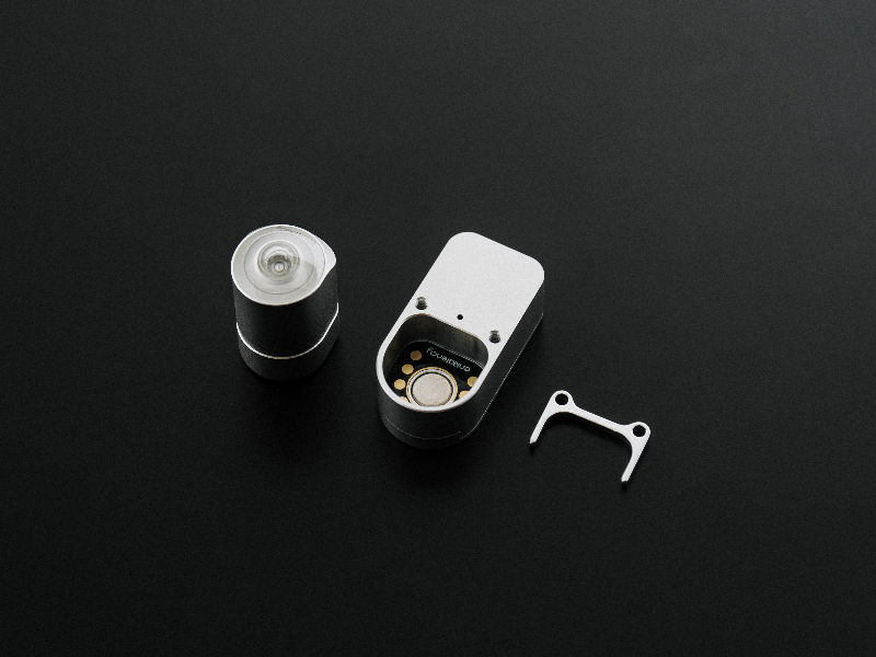
The Alt Bracket will help you avoid both total and short-term loss of connection between a socket and the Alt because of active movement or accidental exposure to physical force. This way you will avoid losing tracking data.
A continuous connection between devices ensures an uninterrupted tracking data transmission. Thus, you receive a full amount of the aforementioned data.
The Alt Bracket will help you avoid both total and short-term loss of connection between a socket and the Alt because of active movement or accidental exposure to physical force. This way you will avoid losing tracking data.
To secure the Alt Bracket, you need to: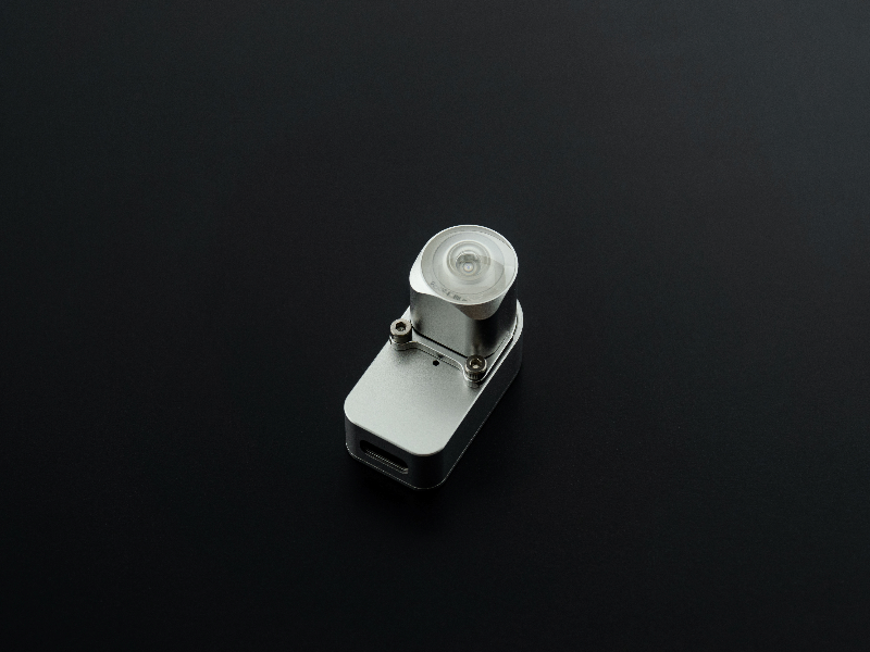 Download the 3D model of the Alt Bracket to your device by clicking the button below.
- place the Alt Bracket under the Alt the way it holds the device on three sides;
- fasten the bracket with M2x4 DIN 912 screws (use the mounting holes).
Download the 3D model of the Alt Bracket to your device by clicking the button below.Compatibility with VR equipment
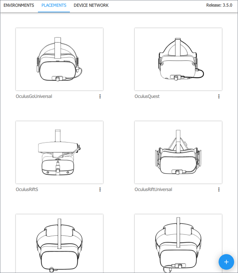
The Alt, when combined with different sockets, is compatible with a wide variety of hardware, particularly with most VR headsets.
For joint use, set up the tracker’s Placement on the HMD (or another VR hardware) in the AntilatencyService. You can select default placement, available for most HMDs, or set up a custom placement.
We are developing special solutions for some devices, for example, Pico Native Socket.
Antilatency tracking can be integrated with a VR headset’s own tracking system. To do this, use Antilatency Tracking Alignment Library.
Tracking reliability
Tracking system needs to detect at least one unique optical pattern in order to determine the position and orientation of the tracker and begin object tracking.
Sometimes the optical sensor can’t detect patterns, for example, due to the user obstructing the view of the markers during the game. In this case, tracking will not malfunction, because the system can determine the position of the tracker with its inertial sensors.
The inertial data provides tracking for enough time to acquire a new image from the optical sensor and resume optical tracking.
Tracker sensors
An optical-inertial module of the Alt contains:
- An optical sensor: an infrared camera covers an area of 230 degrees. Good visibility of the markers in the tracking area ensures stable tracking of the object’s position in space.
- Inertial sensors: an accelerometer defines the linear acceleration value, a gyroscope — the angular velocity. Inertial tracking is autonomous, i.e. doesn’t require external reference points or signals.
Combining all sensors in one device ensures their synchronization.
Low latency
The frequency of receiving data from sensors is different:
- An optical sensor transmits data at
60fps in full-frame. The frequency may be increased up to400fps using ROI (region of interest) techniques. - The frequency of data acquisition from an accelerometer and a gyroscope is around
2000measurements per second.
Sensor fusion puts down precise timestamps for receiving data from each of the sensors.
Shooting the frame and its processing in the optical sensor takes a certain time that depends on exposure time. About 30 IMU measurements are made in the gap between the end of frame processing and receiving new optical data.
This reduces the data update time to
2 ms.Sensor fusion
The Alt uses a sensor fusion approach that forms a combined data stream. It’s based on the sensor fusion data: inertial data is used as a foundation, and is then corrected when the next optical measurements are received.
Due to this correction, the noise inherent in inertial tracking doesn’t accumulate. The correction is not performed separately for each optical data update but takes into account previous measurements. In other words, there is the smoothing of a certain amount of historical data, where recent observations weigh more than older ones.
The
getState method is used to correct the state where a period of historical data is sent as a parameter. The regular value for this variable is the DefaultAngularVelocityAvgTime constant.Thus, tracking data has low latency due to inertial measurements on one hand, and high accuracy due to information from the optical sensor on the other.
Data extrapolation
Sensor fusion data not only contains information about the current position but also predicts (extrapolates) future positioning data: position, rotation, and motion parameters of the tracked object. Data extrapolation allows compensating for the latency that inevitably occurs during rendering.
To get an extrapolated state the
getExtrapolatedState method is used.Note, that the longer the period of extrapolation is, the less accurate the result will be. Therefore, we suggest extrapolating no more than 1 second.
Onboard processing
Transmitting an entire image from an optical sensor requires a high bandwidth connection between the tracker and the host and introduces additional latency.
To minimize latency, the image from the optical sensor is processed directly in the Alt. The calculated coordinates and sizes of markers found in the image are transmitted to the host.
This onboard preprocessing reduces the load on the host device and the communication channel.
Moreover, the resulting optical image is processed by parallel algorithms. They recognize groups of pixels that likely correspond to markers. Image processing is performed when data is read from the optical sensor, so there is no need to store the entire frame in the tracker’s memory.
This approach significantly reduces the computational complexity of subsequent processing of the tracking data. It also decreases the memory requirements of the tracker’s storage device.
Custom optics
The optical sensor receives information through a custom-designed factory calibrated lens with
a
a
230-degree field of view. Good visibility of the markers provides stable and accurate tracking.Be careful when handling the Alt, because small scratches and chips on the glass may reduce the sensor’s visibility.
The scheme of a lens’ FOV:

Coordinate system
The Alt’s coordinate system:
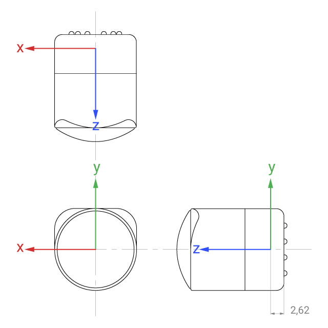
Pay attention to the location of the origin: it has an offset relative to the back of the tracker. Learn more: Placement.
Technical specifications
Optical sensor, accelerometer, gyroscope | |
Tracking frequency | Optical sensor: 60-400 fps Inertial sensors: 2000 Hz |
2 ms | |
Optics FOV | 230° |
Power consumption | In tracking mode: 175 mA @ 3 V In idle mode: 130 mA @ 3 V |
Connectivity | Provided by Socket |
Operating temperature | +5°C — +50°C |
Humidity | ≤75% (+25°C) |
Dimensions | 16 × 16 × 21 mm |
Weight | 10.5 g |
3D model
You can download Alt’s 3D model by clicking
Download button:LED signals
When the Alt is connected to power, the LED indicates the current state of the tracker.
Normal states:
| Indication | Description |
|---|---|
Loading — the initial state when an Alt is powering up or rebooting. During this stage, peripherals are being initialized and the settings are applied. | |
Idle — an Alt in the standby mode, waiting for a task. | |
Task running — an Alt is executing a task. This could be a Tracking task, a Property task, or any other available task. |
Bootloader States:
The Alt enters bootloader mode while updating the firmware or if the firmware is missing or damaged.
| Indication | Description |
|---|---|
Normal — the bootloader is ready to work. |
Read here to learn more about other indicator states of the Alt tracker: Alt: error color codes.
Additional software properties
You can add and customize additional configuration properties for the tracker. They allow you to change the camera exposure or temporarily set an arbitrary color for an Alt's LED. See Alt: additional properties for details.