How to configure Antilatency wireless devices
This is the manual for configuring radio devices to operate in both single and multi-user scenarios. Correct device configuration allows you to minimize the influence of different radio devices on each other and losses due to radio noise.
In this article
Before you start:
Find out how to configure device properties using the AntilatencyService app,
Learn about the available radio channels, restrictions, and recommendations in the Antilatency Radio Protocol.
Find out how to configure device properties using the AntilatencyService app,
Learn about the available radio channels, restrictions, and recommendations in the Antilatency Radio Protocol.
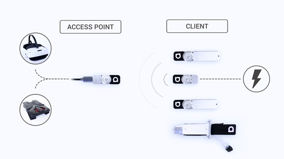
To determine their roles in relation to the Antilatency Radio Protocol, Antilatency devices are divided into two groups:
- an
access pointreceives tracking data from connected clients and transmits it via USB to the Host along with its own data; - a
clientconnects to an access point and transmits tracking data from an Alt.
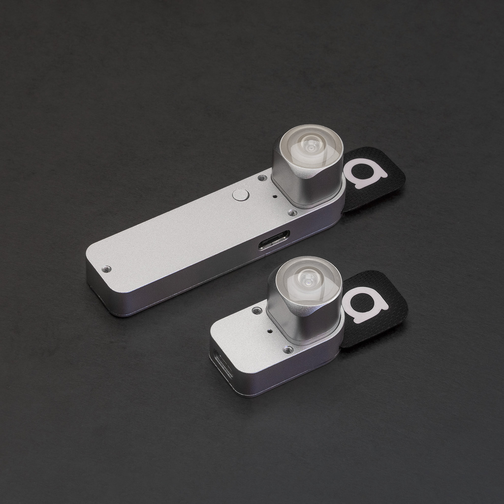
Access points include: Universal Radio Socket and other Pico sockets. Clients include: Tag, Bracer, Universal Radio Socket.
Universal Radio Socket supports both an access point mode and a client mode: to learn more.
Examine the configuration properties below and then proceed with the setup of either a single kit (one access point & several clients) or multiple kits.
Access point properties
RadioChannel
Sets a specific channel that will be used as an access point. With it, you can select a less noisy channel or set up several access points on different frequencies.
The default value is
Sets a specific channel that will be used as an access point. With it, you can select a less noisy channel or set up several access points on different frequencies.
The default value is
-1: the access point will select the first available radio channel from those available by default (refer to Antilatency Radio Protocol).ConnLimit
Sets the maximum number of clients that can connect to this access point.
Sets the maximum number of clients that can connect to this access point.
A value of
0 completely shuts down the radio connection on the device.We highly recommend setting this value to exactly match the number of the client devices you will connect to the socket. The traffic is divided equally by the amount specified in
ConnLimit. Therefore, if you connect fewer devices, some of the traffic will be wasted.Client properties
MasterSN
Ensures that the client only connects to the specified access point. You can set the MasterSN property in different ways.
Ensures that the client only connects to the specified access point. You can set the MasterSN property in different ways.
If the value of the
MasterSN property is empty, client devices will connect to the nearest access point.MasterSN can be omitted, for example, if you only use one access point at a time, or if only one radio channel is used for each set of radio devices. This allows you to quickly replace a client or an access point in a set.
In other cases (two or more access points, several channels in
ChannelsMask, etc.) you should set the appropriate MasterSN to each client.ChannelsMask
Sets the channel mask for the client to search for an access point connection. ChannelMask is a 141-symbol string (corresponding to the number of available channels) that consist of 0's and 1's, where
The default channel mask looks like this:
For your convenience, there are aliases that you can also use:
Sets the channel mask for the client to search for an access point connection. ChannelMask is a 141-symbol string (corresponding to the number of available channels) that consist of 0's and 1's, where
1 indicates that the respective channel will be used while searching for an access point, while 0 means that the channel will be ignored. The string is a bitmask: the channels are written in reverse sequence. The first symbol in the string corresponds to the last 140th channel, and the last symbol in the string corresponds to the 0th channel.The default channel mask looks like this:
000000000000000000001000001000000000000000000000100000000000000000000000001000000000000000000000001000000000000000000000000000000000000000000For your convenience, there are aliases that you can also use:
full— all channels can be used for searching;default— only five default channels can be used for searching;N— only one channel is used for searching. Use the channel's number instead of N.
The fewer active channels there are in the mask, the faster the access point search is.
We recommend to set only one radio channel in the clients mask for the desired access point to operate in. For example, set
120 in the ChannelsMask property of the client devices and 120 in the RadioChannel property of the access point.Setting up a single kit of radio devices
This setup is enough if you're only using one access point and no more than 4 clients. It requires default property values (factory settings):
ChannelsMask = default for the client device, RadioChannel = -1 for the access point.Pay attention to the LED indicator on each device. It denotes different states and processes of the device: the search for an access point, the presence of connected devices, an occupied radio channel and other states. Refer to the description of different indicators on the device page in the Hardware section. For example Pico Native Socket, Tag.
- Connect the access point to the Host.
- Open the AntilatencyService app.
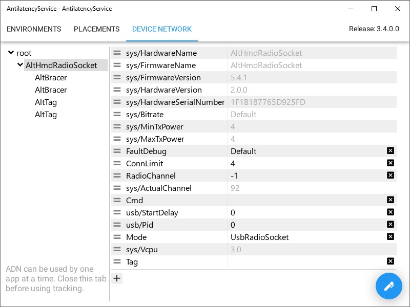
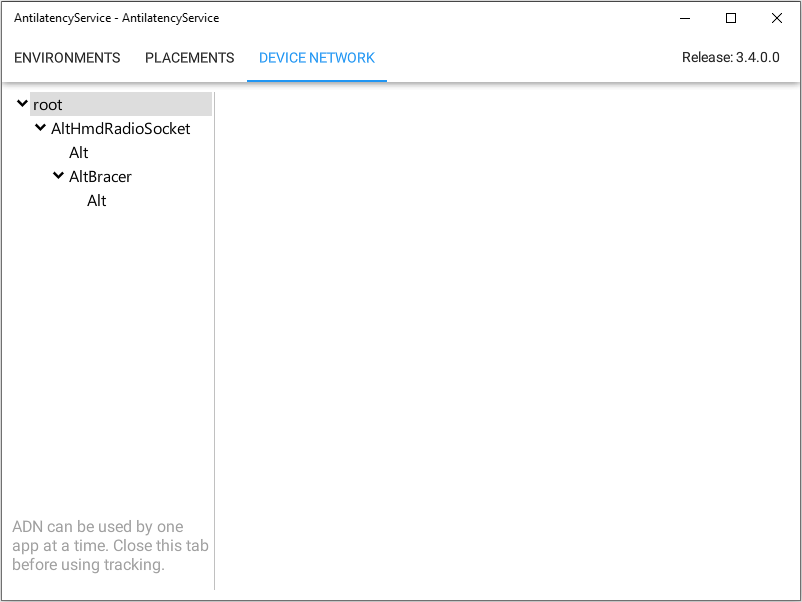
- Go to the Device Network tab.
- Select your device in the Device Tree.
- Set the
ConnLimitequal to the number of client devices that you will connect to this access point (refer to properties). - Send the settings to the device (refer to instructions).
- Turn on the client devices (short press a button on each device).
- After a few seconds, the clients should be displayed in the Device Tree. If any client is not displayed, reconnect it.
- Done! The configuration of a single socket kit is completed.
Setting up multiple kits of radio devices
If you use several access points in the same space, you need to configure each kit of sockets separately.
Pay attention to the LED indicator on each device. It denotes different states and processes of the device: the search for an access point, the presence of connected devices, an occupied radio channel and other states. See the descriptions of the different indicator states on the device page in the Hardware section. For example: Universal Radio Socket, Bracer.
Split the sockets among the kits (an access point & its clients). Make sure that they are all turned off, and start configuring the first kit.
- Select the radio channel for the current socket kit to operate on. Learn more.
Take into account the specifics of several access points operating within one room (refer to Antilatency Radio Protocol). - Connect the access point to the Host.
- Open the AntilatencyService app.
- Go to the Device Network tab.
- Select your device in the Device Tree:
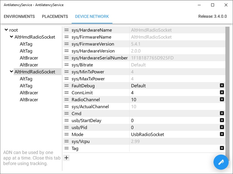
- set the
ConnLimitequal to the number of clients that you will connect to this access point (refer to properties); - during setup time only: set the channel to
92in theRadioChannelproperty; - send the settings to the device (refer to instructions).
- Turn on the client devices (short press the button on each device).
- After a few seconds, the clients should be displayed in the Device Tree. If any client is not displayed, reconnect it.
- Select each client of the current access point and configure its properties:
- set the
MasterSN(refer to instructions); - set the
ChannelsMask(for example, the selected channel only; refer to properties); - send the settings to the device.
- Select the current access point in the Device Tree:
- set the selected channel in the
RadioChannelproperty; - send the settings to the device.
- Make sure that the entire socket kit is displayed in the Device Tree.
- Done! The configuration of the current kit is completed. Turn off the clients (press the button on each device) and disconnect the access point.
- Proceed to configure the next socket kit, starting from step 1.
After setting up all the kits individually, you can start testing the entire system with all devices operating together.
For testing purposes only: if you are using less than 5 access points in one space, you can leave
ChannelsMask = default for all clients, and RadioChannel = -1 for all access points. But you have to set the appropriate MasterSN for the clients.Selecting radio channels
141 radio channels are available for the access points to operate on. Besides the default channels, you can choose any of the other ones (but using some may be prohibited in your country, learn more here). The selected channels must operate with at least 6 MHz spacing: e.g. 0 and 6 is good; 0 and 5 is bad.
To select the optimal radio channels, we recommend scanning the 2.4 GHz range in the tracking area using RadioScanner or a similar program. Run several tests at different positions within the tracking area.
Select one or more of the lesser-used radio channels from the test results. Check an example of analyzing radio scan results on the RadioScanner page.
We do not recommend using channel
92 for operation. It is reserved for connecting client devices with an unknown channel mask.After that, proceed to configure the access points and clients for operation (see above).
Occasionally perform repeated radio scans in the area at different times and in different spots.
There is no guarantee that the selected channels will work without interference over an extended period, the intensity of the radio noise may change due to various factors.
How to set the MasterSN property
You can set the MasterSN property in two ways.
- First — by using the power button on the device.
Connect an access point to the Host.
Then turn on the wireless socket and wait till it connects to the access point. The LEDs of both devices will be blinking evenly, with the same color.
Press and hold the power button on the wireless socket for about
5 seconds. After that, the wireless socket will be restarted and serial number of the access point will be automatically saved to the MasterSN property.- Second — by using the AntilatencyService app.
Go to the Device Network tab. Find the access point in the Device Tree and copy its serial number from
sys/HardwareSerialNumber.Then, find the client and paste the this serial number to the
MasterSN field.Send the new settings to the device. To learn more about how to edit, create, and delete properties, follow this link.
How to reset the MasterSN property
Turn on the wireless socket and press the power button for
5 seconds. After that, the wireless socket will be restarted and the MasterSN property will be erased.To find out whether the MasterSN property is set on the device, check the indicator:
| Indicator state | State of the device |
|---|---|
Client is trying to find an access point to connect to. | |
Client is trying to find a specific access point ( MasterSN property is not empty). |
Reconnecting to the access point
In some cases, the client cannot connect to the access point and is not displayed in AntilatencyService Here are possible causes and solutions:
- The
MasterSNproperty on the client is set to an unknown access point or lost.You can reset the MasterSN using the power button, and, if necessary, set a new property value. - The client has an unknown channel mask (
ChannelsMaskproperty).To solve this problem, set the access point to channel92in theRadioChannelproperty. This channel is always available for searching and cannot be reset. - The access point is experiencing radio interference on a selected channel.Perform a RadioScanner in your location and use the results to change the RadioChannel on the access point and
ChannelMaskproperty on the client accordingly. - The access point has reached the limit of connected clients.Increase the
ConnLimitvalue or turn off one of the previously connected clients. In case there are 4 clients already, we recommend using another access point. - Device Network does not show any devices.Only one application can use the Antilatency devices at a time. Close all other applications that may use the ADN. For example, this could be a running project in Unity or a running RadioScanner utility.
See more about the problems with wireless devices' connection and how to solve them in our video: