How to add the tracking system into Stage Precision application

In this guide, you will learn how to quickly and easily integrate the Antilatency tracking system into Stage Precision applications: the required settings in AntilatencyService and step-by-step actions in SP Studio program.
You may watch the short video tutorial at the end of this article.
You should go through the following steps:
You need AntilatencyService (version 4.0.0) to be installed and running on the same computer where SP is running.
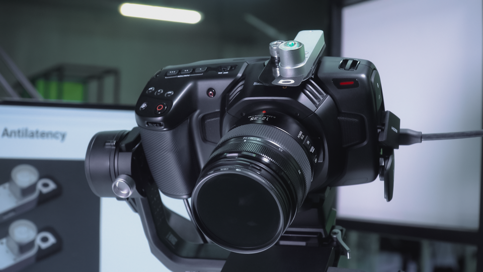
Attach the Alt tracker to your camera and set up its connection
The placement of the socket with an Alt on a camera body depends on the type of Antilatency tracking area. For example, you should choose a place on the bottom of the camera for a floor tracking area, or on top of the camera for a ceiling-based tracking area. Attach the socket to the camera with duct tape for example, and insert an Alt into it.
Now set a wired or wireless connection that your socket supports. Follow this guide to configure wireless sockets.
Use Device Network tab of AntilatencyService to check sockets' and Alts' connection.
Remember: Antilatency devices could be used only by one application. Therefore you should leave the Device Network tab before running SP's application.
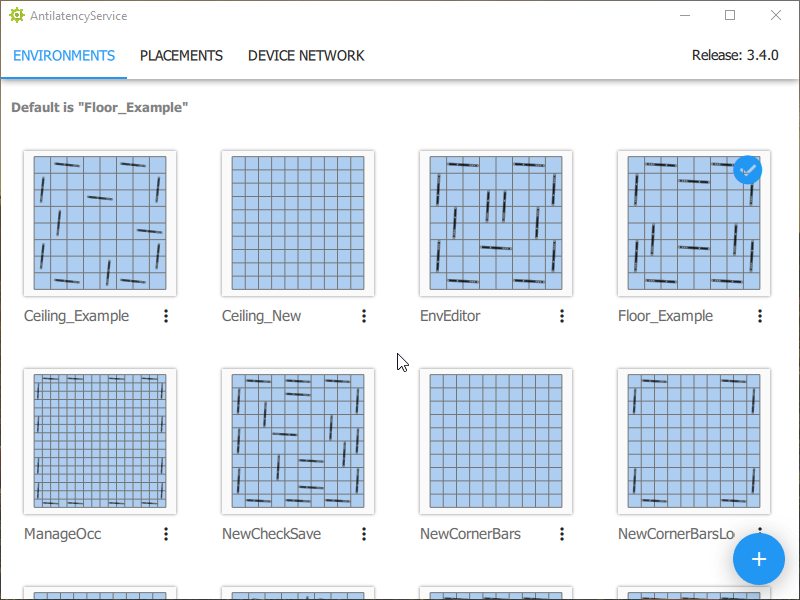
Set a default Environment in AntilatencyService
If you haven't set up a tracking area yet, then follow this guide: Tracking areas setup.
Now you should open AntilatencyService and set your Environment as a default tracking area.
Configure SP software
Open the Stage Precision software. In this guide, we use SP Studio.
Setup Antilatency connection
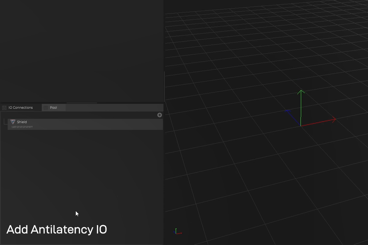
Add the Antilatency IO:
- click on the "+" icon in the IO Connections section, open 3D Tracking, and select antilatency;
- OR right-click on the IO Connections section and add antilatency using search (type "antilatency").
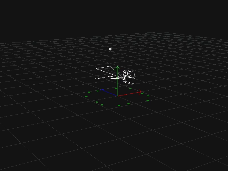
If the connection is successful, the IR markers of your tracking area will be displayed in the Viewport section, as well as their coordinates in the Environment tab of the Inspector section.
If you have no connection to AntilatencyService, check the LOG within SP.
If you see the Failed to load AntilatencyDeviceNetwork library message, then disable your firewall or add AntilatencyService to it.
If you see the Failed to load AntilatencyDeviceNetwork library message, then disable your firewall or add AntilatencyService to it.
You may need additional information:
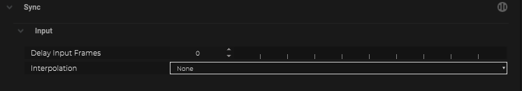
- Options for Input Interpolation
Add objects from the IO
Make sure that the Alt and the socket on the camera are turned on and ready to work. To add the objects from the IO:
- Click the search icon in the Inspector section and click on each sensor (corresponding to Alt-trackers). These sensors' names are the serial numbers of each Alt.
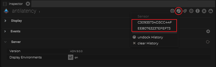
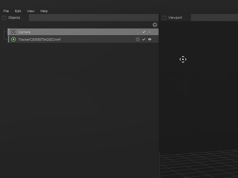
- After adding the sensors check the object tree in the Objects section.
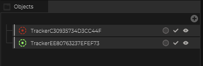 The different colors are an indicator of the tracking state. Red means no tracking, and green means tracking is active.
Thus you have added Tracker Objects with Maps Input to Antilatency.
Maps Input
Instead of adding an object from the Antilatency IO, it´s also possible to add Maps Input directly into an object from the object tree.
Select an object, navigate to Maps Input and click on the "+" icon to add the antilatency Map.
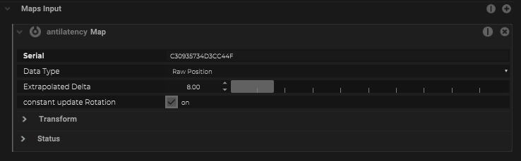
| Name | Description |
|---|---|
Serial | The Serial number of the Antilatency Camera. (Will be created automatically when using the magnifier inside the IO) |
Data Type |
|
Extrapolated Delta | Delta value of extrapolation when used as Data Type |
constant update Rotation | Use rotation from the IMU as well, when the position is not detected |
Tracker and camera matching
Enable an object corresponding to the tracker on the camera only. It will appear in the Viewport section.
Choose the Camera object in the Objects section and turn its display mode on. Then drag the Camera object onto the Tracker... object to link them.
Choose the Camera object in the Tracker... object. Go to the Inspector section, then right-click on the Position field of the Coordinates tab and click Reset value.
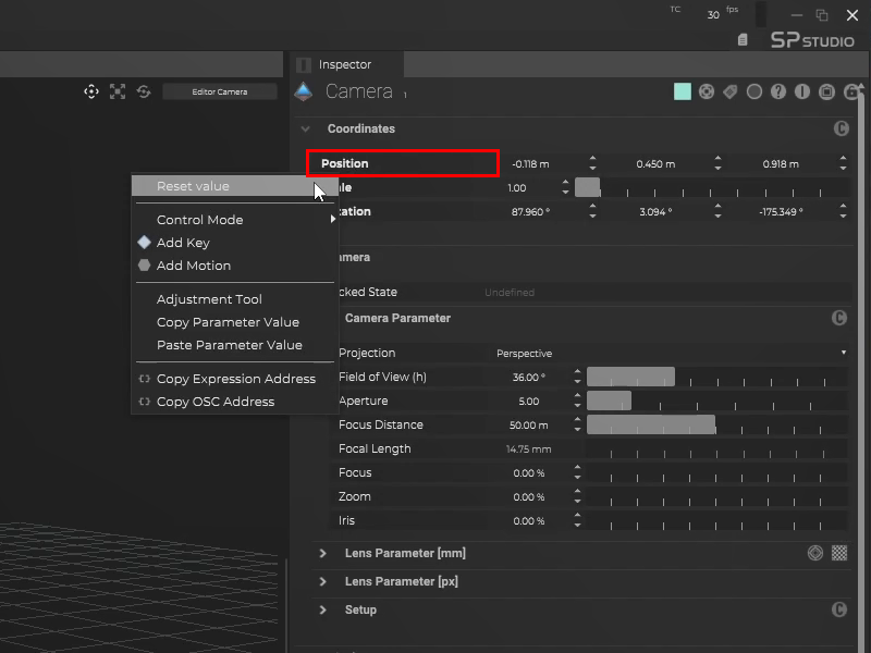
Now the camera and the tracker are matched and ready to work.
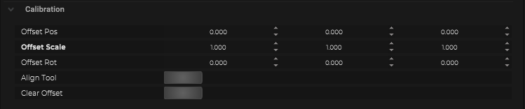
With SP, you can calibrate the whole camera system, including tracking and nodal offsets for the best tracking results. To do this, use Camera Alignment and advanced SP calibration tools like Lens Calibration system.