Pillar tracking area
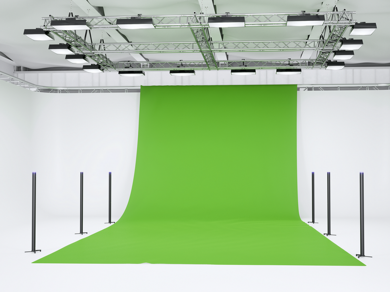
The pillar tracking area is a kind of vertical Environment. It's optimal for mobile projects with a temporary location. IR markers are installed in vertical reference bars
(pillars), which are positioned freely in the room and independently connected to power supplies or power banks.High quality and speed of tracking
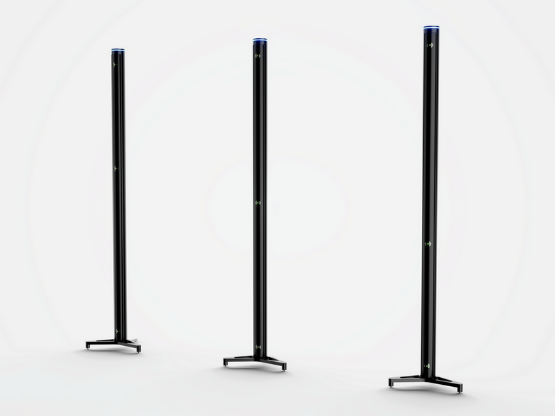
The horizontal orientation of the IR marker beams provides better visibility than in the case of flat tracking areas. Vertical Environment supports 3 kinds of Antilatency Pillars (with different heights of the central IR marker). Thanks to this, more features are formed and the Alt tracker determines its position faster.
The Vertical Environment requires more resources and time to calculate a feature. For this reason, a limit of no more than 50 pillars is introduced for one Environment.
Versatility
Unlike others, the Vertical Environment takes into account the room geometry, occlusions, narrow corridors, and different levels as much as possible. Pillars can be installed at various heights, not only on the floor.
Mobility
The Pillar tracking area is compact, easy to transport, and does not require significant time and effort during installation and configuration. It can be set up by a single person.
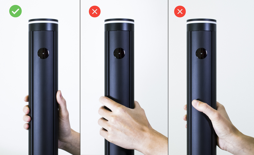
When transporting and moving reference bars, special clamps must be used to protect the suspension with IR markers from deformation. Remove the clamps only after completing the assembly of the reference bars and their positioning within the tracking area.
Regardless of whether the transport clamps are mounted or not, the reference bar can only be held by its housing (from the back of the pillar). Do not press on the suspension with IR markers to avoid damaging it.
Easy to install
The tracking area is ready for use immediately after being assembled and turned on.
Additional steps are required only when setting up a tracking area for the first time or setting up a new configuration:
- arrange reference bars according to a pre-selected or arbitrary pattern;
- activate the alignment of reference bars by moving your hand over each pillar;
- measure the distance between pillars and enter them into AntilatencyService;
- test the tracking area;
- if necessary, calibrate the tracking area in AntilatencyService.
When using the tracking system, try not to get close to the reference bars to avoid knocking them down. Tracking close to reference bars will work worse than tracking at a distance of more than 1 meter.
Standalone and ease of connection
A USB type-C charger is used as a pillar’s power supply. Through the same connector, pillars are connected to a PC for firmware updates. Pillars’ locations do not depend on each other. This allows you to create complex tracking areas.
Pillar design
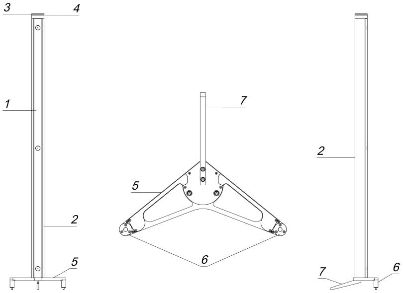
The pillar consists of the following elements:
- suspension with IR markers;
- housing;
- sensor;
- circular RGB LED indicator;
- pillar base;
- adjustable legs;
- fixed leg.
The pillar housing is fixed with 3 screws in the base and one additional screw for the fixed leg. The base contains a board with a magnetometer, and electric motors in the adjustable legs, which are used to adjust the length of the extension rods.
Pillar alignment
Activation of the sensor automatically starts the alignment procedure for the reference bar. By adjusting the rods’ length using the motors, the magnet at the bottom of the pillar is aligned to the magnetometer’s center. The alignment is performed once when the pillar is initially turned on. The procedure must be repeated if the pillar is moved.
For more information about pillar alignment, refer to How to set up a pillar tracking area.
Default kit
- 4 pillars;
- 4 pillar bases;
- fastening screws (3 items in the base cap and 1 item for the fixed leg for each pillar);
- Allen wrench;
- 4 platforms (layout plates);
- 4 USB Type-C cables for USB charger.
Pillar technical specifications
Indication | circular RGB LED indicator |
Connectors | USB type C (power supply and data transmission) |
Supply voltage | 5 V, 1 А current |
Operating temperature | +5°C — +50°C |
Humidity | ≤75% (+25°C) |
Pillar housing overall dimensions | 1428 × 67 mm |
Pillar base overall dimensions | 300 × 257 × 79 mm |
Weight | 3.4 kg |
Viewing angle of IR markers | 170° |
We recommend using power supplies with a reserve of characteristics, for example, 5 В - 2 А or more.
LED signals
| Indication | Description |
|---|---|
Reference bar is ready | |
Reference bar alignment is needed | |
Reference bar is aligning |