How to create a Vertical Environment for your tracking area
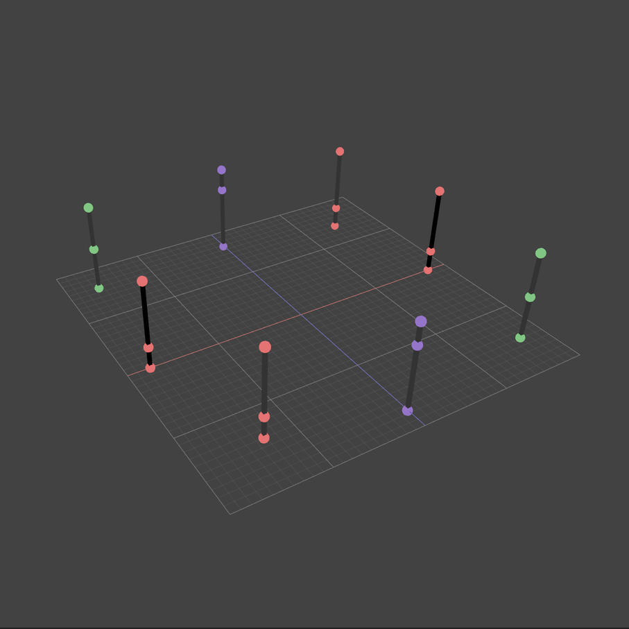
This section describes the creation and configuration of the Vertical Environment. Like the horizontal Environments, the vertical ones are made up of IR markers, combined into reference bars. Markers can be placed directly on walls, special racks, planks, and pillars. Reference bars should be in a strictly vertical position.
Table of contents
Creating an Environment in AntilatencyService
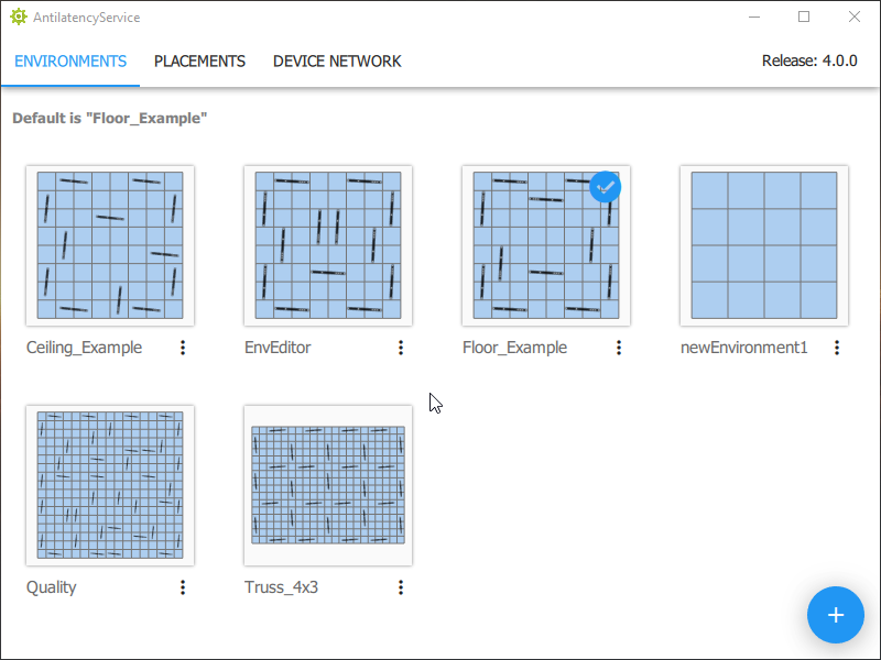
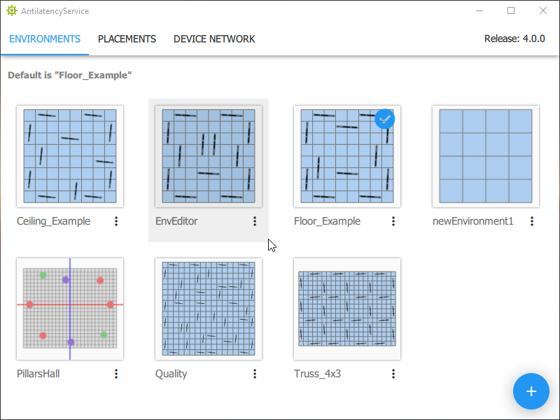
To create a new Environment in AntilatencyService, click the
+ button in the window's lower right corner and select the New Environment menu item. Then specify the Environment's name and select the Pillars type. It is recommended to use the Antilatency preset to load the branded reference bar settings.We suggest using the standard preset. If you want to create custom reference bars having non-default parameters, then before installing the tracking area, make sure to contact our support team to check the Environment scheme and the operability of the planned tracking area.
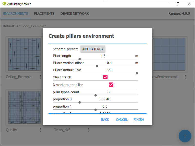
You can reject the manufacturer's suggested values and adjust the reference bar parameters by yourself:
- select a reference bar template with two or three IR markers (
markers per pillar); - set a bar length (
pillar length); - determine the number of bar types (
Pillar types count) and proportions for each type (Proportion #).
The system supports various IR marker placements within the reference bar. Thanks to this, unique combinations (features) are formed, which allow the tracker to quickly and accurately determine its position in space.
The first and last IR markers are located at the lowest and highest points of the reference bar respectively. The proportion determines the position of the middle IR marker relative to the first (lowest) one. The proportion value is the ratio of the distance between the lowest and middle IR markers to the length of the reference bar (that is the distance between the lowest and highest IR markers).
In addition to these parameters, in the Vertical Environment scheme you can configure:
- height of the lower IR marker above the floor level (
Pillars vertical offset); - viewing angle of IR markers (
Pillars default FoV) – applies to all reference bars, but only when creating an Environment. After - only separately for each reference bar; - accuracy of marker search algorithm (
Strict match). Strict match mode should be enabled when the tracker “sees” strictly the current tracking area (typical use cases). Strict match mode should be disabled if extra reference bars can be visible to the tracker, like in these cases:- two vertical tracking areas, in particular the Pillar areas, are turned on, and located near each other;
- there are large reflective surfaces in the room (for example, glossy tiles, glass or mirrored walls) in which reference bars are reflected.
Let's take a 1.3-meter long reference bar with three markers as an example. By default, the system offers to use 3 bar types with different proportions.
Placing the reference bars in the editor
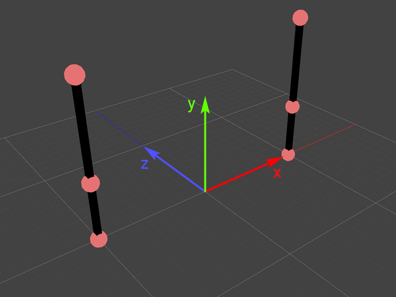
After defining the parameters, the main editor window will open. It uses the three-dimensional coordinate system (X, Z, Y), as shown in the figure below. The size of the main cells is 1 × 1 m.
Controls in AntilatencyService:
- use the mouse scroll wheel to zoom the Environment in/out;
- click and hold the middle mouse button to move the visible part of the Environment;
- hold the right mouse button to change the tilt angle;
- double-click the right mouse button to return to the default view.
The Vertical Environment already includes 2 reference bars defining the area center. They differ from the rest of the reference bars added by the user. The first pair can only be moved synchronously along two axes (X, Y) of the three available (X, Y, Z). This is to maintain the Environment center during editing and optimization. These reference bars can be of different types.
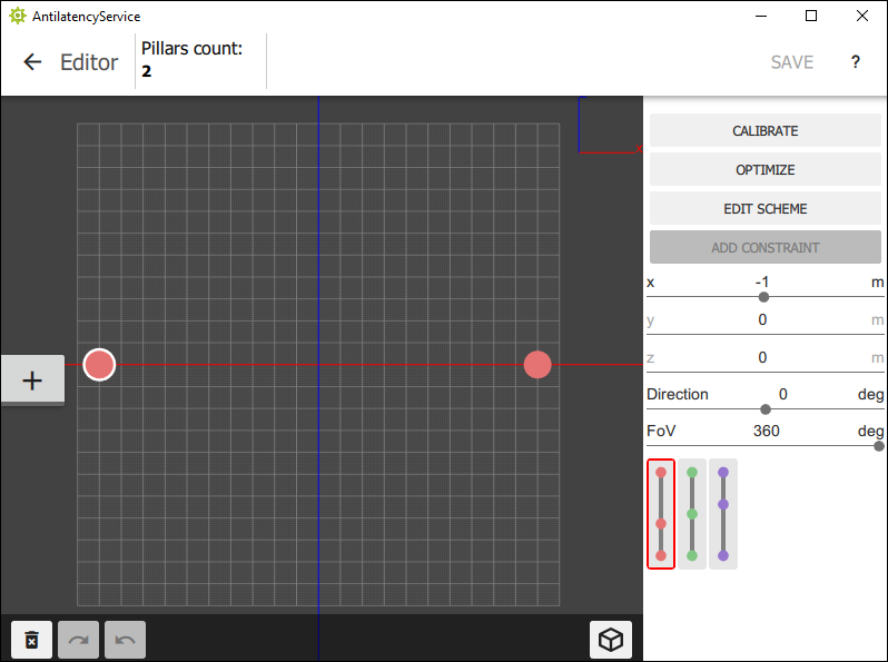
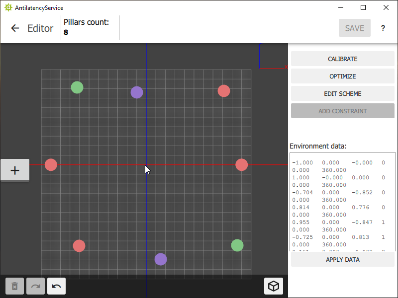
Next, you need to indicate the approximate location of the remaining reference bars. To do this, use the
+ / Add Pillars button in the window's left side. When you click on the button, it will be underlined with a red line, and the system will offer possible bar types (which were defined by the user during the initial setup).Place different reference bars within the Environment (based on their physical placement).
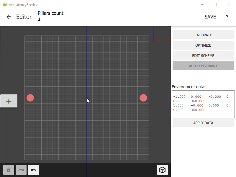
Save the draft of the Environment with the
Save button located in the window's upper right corner. The coordinates and type of each reference bar will be displayed in the Environment Data table below.Changing the direction and viewing angle of IR markers
In AntilatencyService version 4.0.0 and higher, you can adjust the direction and viewing angle of IR markers on reference bars. This allows you to create an Environment with a smaller number of reference bars or even just a pair of bars of the same type, ensuring the uniqueness of the features they form.
- To change the viewing zone of the markers select the reference bar, then, holding down the
Ctrlbutton, adjust the angle with themouse wheel. By default, reference bars have a 360° angle.The viewing angle of branded reference bars' IR markers is 170°. - To set the direction of the reference bar hold down the
Ctrlbutton,left-clickon the selected reference bar, and drag in the desired direction.
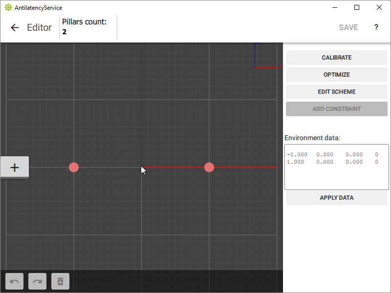
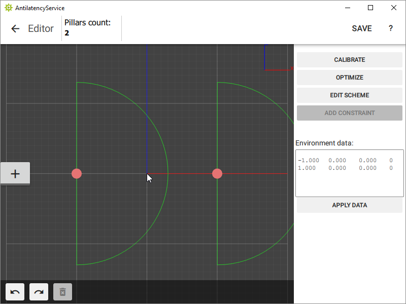
If tracking works well without the bars' viewing angles having been limited, then you do not have to specify their FoV and directions. Otherwise, it is better to allow for a bigger margins, since errors with direction or markers’small FoV can lead to tracking errors.
The Vertical tracking areas (Pillars) created in AntilatencyService 4.1.0 will not be supported in the previous versions of the application.
Changing the reference bars’ position in the editor
The reference bars' position can be adjusted in two ways:
- in the visualization window by simply moving the mouse;
- in the
Environment Datawindow by entering the required values.
Column number | Value |
1 | X axis coordinate |
2 | Y axis coordinate (height above floor level) |
3 | Z axis coordinate |
4 | Bar type (0 — the first type, 1 — the second type, 2 — the third type) |
The units of measurement are meters.
After adjusting the position of reference bars, click on the
Apply Data button.Starting from version 4.1.0, you can change the vertical offset of all reference bars above the floor level so that the floor level in the virtual world matches the real one. For Antilatency Pillars, this is the height from the bottom of the reference bar’s base to the lower IR marker (0.114 m). For reference bars without a base (for example, planks) use the distance between the lower IR marker and the floor.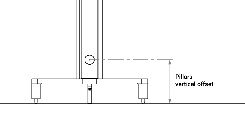 To do this, click
To do this, click Edit scheme in the editor and set the value in meters in the Pillars vertical offset parameter. Now, when you change the additional vertical offset of an individual reference bar, you will need to count from the floor to the base of the reference bar.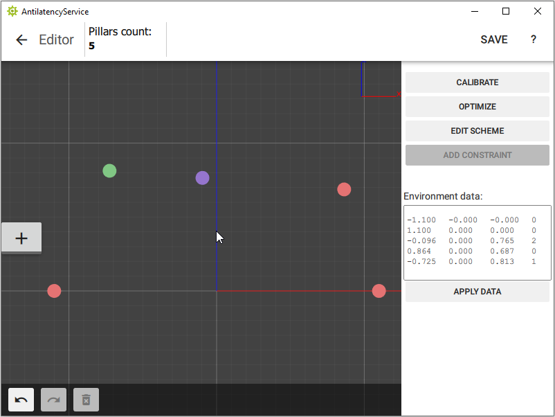
Optimizing reference bar placement
Next, you need to optimize the Environment so that the position of the reference bars within it corresponds to the actual one. For this purpose, use the tool for distance limitation
(constraints).Use a tape measure to estimate the actual distance between 2 neighboring bars.
You should measure the distance taking into account the direction of the bars (IR marker orientation) as shown in the figure. If the reference bars are at different heights, then the distance is measured simply at the same height from the floor. For convenience, we recommend using a level (laser level).
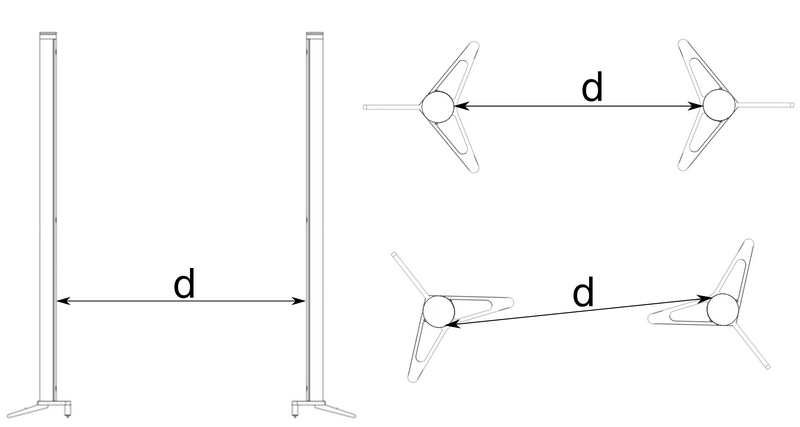
Do not press on the IR markers suspension when measuring the distance!
For Antilatency Pillars, you can conveniently measure distances using the markings on the platforms: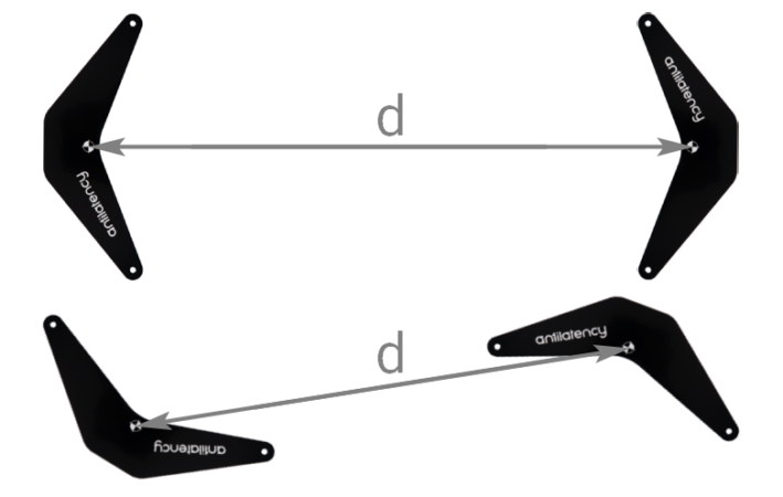
Then, select these bars in the program using the mouse or the Shift + left mouse button combination. After that click on the
Add Constraint menu button (or Ctrl + Q).In the window that appears, specify the measured distance between the selected reference bars.

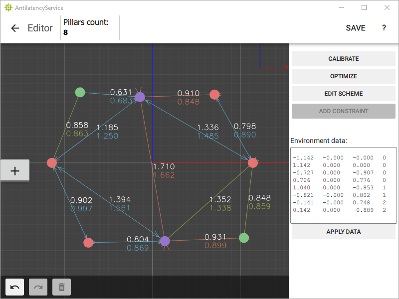
An arrow with dimensions will appear between the reference bars, where the upper number is the measured distance between the bars, and the lower number is the automatically calculated distance on the layout:
- if the distance in the Environment is less than the measured distance, then the line and number will be red;
- if the difference between the distances is within acceptable limits, then the line and number will be green;
- if the distance between the markers is greater than the measured one, then the color is blue.
The arrow with dimensions can be moved.
Repeat the procedure for the remaining pairs of reference bars. You should take measurements so that each reference bar is the vertex of at least one triangle. Thus you form a rigid figure.
An example with the minimum allowed number of dimensions for the current pattern.
The more measurements are the better. We recommend at least three per bar. After adding all the constraints, press the
Optimize button to automatically correct the position.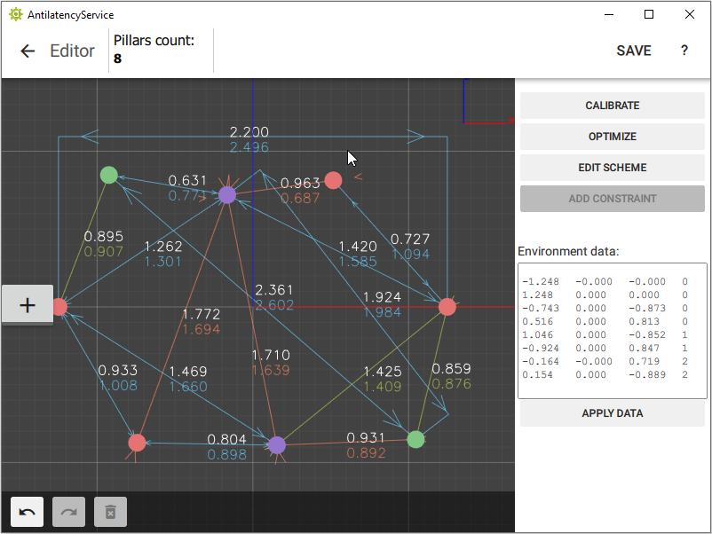
Now the Environment is fully consistent with the arrangement of reference bars in the room. Click the
Save button in the top right corner to save the Environment.Environment calibration
Calibration allows you to make the location of reference bars in Environment even more precise, so that it matches the position of real pillars/bars as closely as possible.
Environment calibration does not replace or override the optimization of pillar placement!
- Go to the
Device Networktab in AntilatencyService. - Turn on the devices, check they are displayed in the device tree. If they don't appear, use the instructions: How to configure Antilatency wireless devices.
- Go back to the
Environmentstab, select your Environment, click⋮, thenEdit. - Press the
Calibratebutton.
Next, take a Tag or a Bracer with an Alt and prepare to walk around the tracking area while calibrating. You must move the socket so that the Alt sees the tracking area from as many angles as possible (different positions and rotations). To launch the calibration procedure:
- Press the
Begin Collectingbutton. - Turn on the socket with an Alt, and walk around the tracking area until you get about a 1000 frames (
Frames countfield). - Press the
Stop Collectingbutton. - Use the
selected samplefield to select positions that look like tracking errors (incorrect peak points in the tracker path) and delete them (Remove selectedbutton). - Now pay attention to the
Mean sqr errorfield. Press theCalibratebutton and then the value ofMean sqr errorshould decrease at least by an order of magnitude, and preferably to0. - If the value in the
Mean sqr errorfield is still much greater than0, do either:- Go back to the Editor and apply the current calibration result, and then perform the next iteration of calibration;
- press
Clear Datasetand repeat the calibration algorithm.
You can see how accurately the beams from the Alt tracker hit the markers by moving the slider along the
selected sample line. If no beam hits markers on a reference bar, then the distances between this and other reference bars should be measured again.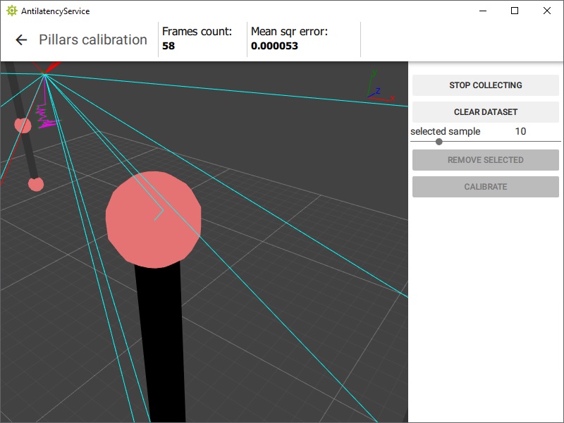
The blue-green beams are used for successfully detected IR markers. The red beams indicate a measurement error. If the tracker fails to detect only one of the three IR markers of the reference bar, all three beams will be shown in red. If the tracker detects more than three IR markers on a single reference bar (e.g. when they are reflecting off of the floor), the beams will be red too. In these cases, it is necessary to re-measure distances and optimize the Environment.
The calibration is successful if most of the beams enter the markers accurately and without deviations. After successful calibration, click the
back arrow, and the Apply button in the pop-up window. Then save the Environment changes (Save button).The calibration of this vertical tracking area is completed.