HorizontalGrid Environment
HorizontalGrid Environment structure
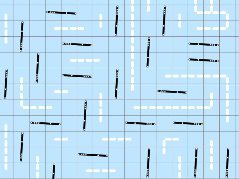
The peculiarity of Horizontal Grid Environments is that the IR markers must be placed crossing the cells grid. Any grid cell size can be used, but the default is 0.6×0.6 m.
The standard HorizontalGrid Environment reference bar consists of three IR markers connected in series. The figure below shows an example of the location of reference bars for a floor tracking area.
It can be seen that by default the reference bars do not lie on the same line, but are set at a certain angle relative to the cell edge. Thereby neighboring bars can not form a false patterns when the tracker is looking for reference bars.
HorizontalGrid Environment coordinate system
The HorizontalGrid Environment uses a Cartesian coordinate system. In floor tracking areas the coordinate system origin is situated in the floor plane (marker plane) and corresponds to the geometric center of the tracking area. In ceiling tracking areas the coordinate system origin is also situated in the floor plane, i.e. the ceiling height is subtracted from the geometric center of the ceiling tracking area.
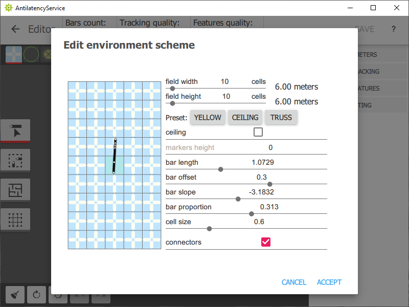
HorizontalGrid Environment parameters
The optimal values of the HorizontalGrid Environment parameters are set by default in the presets for the floor and ceiling tracking areas. If it's necessary, all parameters can be adjusted to suit custom needs, including:
- cell size;
- tracking area dimensions in the cells count and meters;
- bar length;
- bar offset relative to the center of cells;
- bar slope, i.e. the angle between the bar and the cell edge;
- bar proportion, i.e. the relative position of IR markers in the reference bar.
Warning! We suggest using the standard presets. When you create a custom Environment, you take responsibility for the operation of the tracking area. Make sure to contact our support team to check the custom Environment before installing the tracking area.