Socket Reference Design
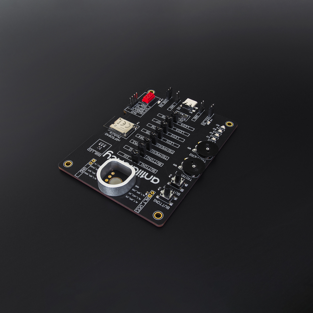
Reference Design
We provide Reference Design materials to help you design your own Socket. You can take the Reference Design as an example and use its modules for your project. The circuitry, a 3D model, a BOM are available to download below:
Main components
- nRF52840 module;
- SWD connector;
- USB connector;
- DC/DC 3V;
- Alt connector;
- RGB status LED;
nRF52840 module
We highly recommend using the nRF52840 module instead of an nRF52840 microcontroller with its required external components. Using the module gives some benefits:
- the module is certified which can accelerate the arrival of your product on the market;
- the reduced BOM means less components, therefore making the board assembly process easier, resulting in fewer mistakes;
- all the external required components are already installed thereby preventing incorrect assembly;
- the market normally offers a range of modules with different antennas or connectors for all tastes;
- some manufacturers offer to preinstall the firmware/bootloader.
Power Supply
The controller and Alt require a 3V power supply. Average consumption is about 200mA when in operation. You need a regulator with at least a 250-300mA current limit. We use a DC/DC NCP1529MUTBG.
The USB module requires a 5V power supply. This input powers only the USB module (less than 1mA).
When using the VCC3V jumper, you can turn off the 3.0V output and connect an external power supply.
USB connector
The USB connector provides a 5V power supply and a connection to the controller to transfer the data, to update the firmware and to set up the device properties.
Use the USB5V jumper if you want to connect your own power supply. When you have no need for USB, for example, when the Socket works in wireless mode, any voltage in the range of 3V — 5.5V can be applied to the VBUS input.
SWD connector
You need an SWD connector only for the first bootloader setup. For further uploading or updating of the firmware, you can use AntilatencyService.
The board has two similar connectors: a MicroMatch FOB.06P and a Pls-4. You can use either of them with your board.
You don't need the connector if your module has preinstalled firmware.
Alt connector
The Alt connector has 8 contacts and a hole for the magnet in the center.
We use magnets that have a diameter of 7mm, 2mm high, and of grade N52. They perfectly match the 6.9mm board hole.
The Alt holder also requires the holes for installation. As a frame for the Alt we use an aluminum holder with 4 feet. After planishing these feet fix the holder on the board. The holder model is available to download:
RGB status LED
The RGB LED allows users to see the state of the Socket. This LED has different display modes. We highly recommend that you do not remove it and use the same LED on your board.
You can choose another LED but make sure their colors correspond.
Antilatency Hardware Extension Interface components
There are 2 buttons, 2 potentiometer trimmers, and 4 LEDs on the board to control using Antilatency Hardware Extension Interface. Each component is connected by jumper so you can take them from the board and use alternatives.
If you don't need the Antilatency Hardware Extension Interface, then just don't use its components and leave the controller's pins free.
Other recommendations for the custom board
If you design your own board please pay attention to the recommendations below.
PCB parameters:
- 2mm height — to install the magnet correctly;
- ENIG — to provide a flat surface, resistance to wear, and the stable connectivity of the Alt pogo pins and the board.
We recommend making the connection between an SPI and the Alt as short as possible and to protect it from electromagnetic interference.
The nRF module's position should correspond to its datasheet requirements. Pay extra attention to the position of the antenna.
Bootloader and firmware
The SocketReferenceDesign dev board comes with a preloaded bootloader and firmware. If you design your own custom board you can download the bootloader below:
Load the bootloader on the board using the SWD pins and a programmer (for example, J-link).
After this, use the USB connector and update the firmware with AntilatencyService.