Extension Module
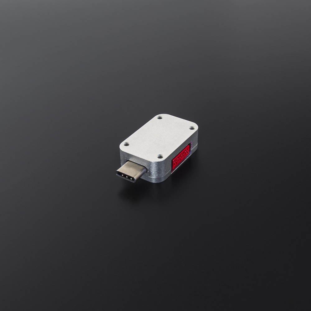
This is a module for connecting to the Universal Radio Socket additional components using the Antilatency Hardware Extension Interface. Using it, you can read the external triggers of buttons or connect additional circuits to the Socket.
Use a USB Type-C cable to connect the Extension Module to the power supply.

Operating Extension Module is only supported by Universal Radio Socket (device version 2.0.0). The socket may be used in any of two available modes: access point and client. Other sockets can neither control nor read data from the Extension Module.
Use the Antilatency Hardware Extension Interface Library for working with this device.
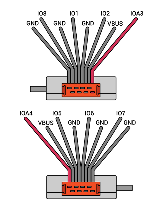
There are 8 pins available for the connection, each of them can operate in input or output mode. Any 2 pins can be set to pulse the counting mode simultaneously. And only 4 among the pins — to PWM mode.
Please note, analog and VBUS pins are located symmetrically on both sides of the board.
| Pin | Input | Output | PulseCounter | PWM | Analog |
|---|---|---|---|---|---|
IO 1 | + | + | + | + | - |
IO 2 | + | + | + | + | - |
IOA 3 | + | + | + | + | + |
IOA 4 | + | + | + | + | + |
IO 5 | + | + | + | + | - |
IO 6 | + | + | + | + | - |
IO 7 | + | + | + | + | - |
IO 8 | + | + | + | + | - |
The maximum voltage on all IO pins is no more than 3 V, and 5 V on the VBUS pins.
IOA3 and IOA4 are low-speed pins. The signal frequency should not exceed 10kHz.
The pins are not protected from static electricity and incorrect connection.
Pin operating modes
Input — an input mode with internal pull-up (≈13 kOhm). The state of the pin is updated every 5ms, and if it has changed, it is sent to the Host.This is a diagram of connecting a button with static electricity protection: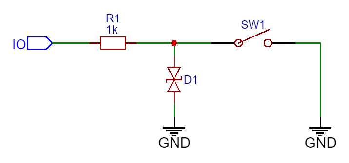
In this diagram, the D1 ESD diode is used for electrostatic protection, and the R1 resistor limits the current and keeps socket pins operable in case of incorrect connection.
Output — a Push-Pull output mode.A typical LED connection diagram:
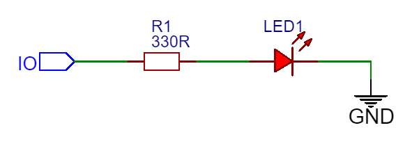
The current consumption from the pin in Output mode must not exceed 4mA.
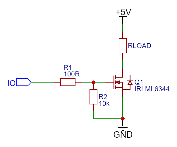
If you need to handle a more powerful load, you can use the diagram:
PulseCounter — a floating input mode used to count the number of rising edges of the signal. Use it to connect other circuits e.g. a capacitive sensor circuit.PWM — a push-pull PWM mode that outputs a PWM signal of a given duty cycle and frequency. It is used to control LED brightness or intensity of vibration. Also, you can use it for connecting circuits, or as analog output using an RC filter.Analog — an analog input mode with a 10 bit resolution.A typical potentiometer connection diagram:
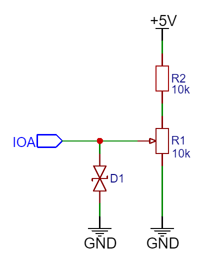
The R2 resistor provides a voltage limitation on the IOA pin. The voltage should be in the 0-3 V range.
Technical specifications
Ports | USB Type-C MICRO-MATCH FOB.08P with 8 pins (part number: 7-215079-8) |
MICRO-MATCH FOB.08P connector | MICRO-MATCH MOW.08P (part number: 215083-8) |
Wire type and gauge | |
Operating temperature | +5°C — +50°C |
Humidity | ≤75% (+25°C) |
Dimensions | 28.7 × 18.2 × 9.2 mm |
Weight | 9 g |
3D model
You can download Extension Module 3D model by clicking button
Download