How to set up a truss tracking area
This section describes the assembly and installation process for a Truss tracking area.
Table of contents
Truss tracking area is one of the Environment types, which consists of Truss Reference Bars connected in series. The reference bars are fixed onto the suspended truss with special fasteners. The kit includes a template for reference bar positioning, H05VV-F 2x1.5 Black cables with GX16 connectors installed (socket).
The set up of the truss tracking area is shown in details in our video.
Trusses specification
To install the tracking area, a suspended truss structure is used. It's assembled by the user from triangular segments such as Global Truss F33250 (or square segments F34250) and 4-way corner junctions F33C41, F34C41 or similar ones (subject to the overall and installation dimensions). These trusses are made up of segments manufactured from durable aluminum alloy EN-AW 6082 T6.
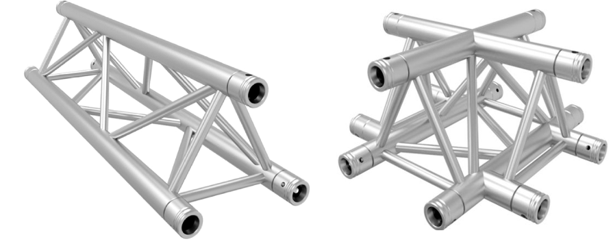
The truss segment F33250 (F34250) length is 2.5 m and the junction F33C41 (F34C41) length is 0.5 m. Thus, the step of the structure is 3.0 m. The diameter of the main pipes is 50 mm, the distance between the pipes centers is 240 mm. The trusses have 4-point anchoring edges for the installation of quick-release couplings.
Please note that the trusses are purchased and installed by the customer on their own. They are not included in the tracking area delivery kit. Before placing the Truss Reference Bars, make sure that the trusses are strictly horizontal.
For truss tracking area setup you will need:
- a HorizontalGrid Environment in AntilatencyService;
- mounted trusses;
- a power supply unit with an output voltage of 18 V. The output current is calculated using the formula
N × 0.17 A, where N is the number of reference bars. We recommend to connect no more than 12 reference bars in one circuit. The total number of reference bars per 1 power supply is no more than 36 pcs.; - a standard cable for connecting to 220 V mains.
Сonfiguring the Environment in AntilatencyService
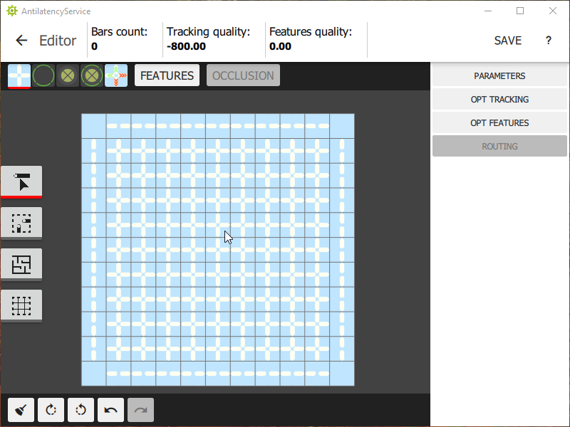
To create or modify the Environment, use the AntilatencyService application.
It is recommended to use ready-made Environment examples for truss tracking areas of various sizes.
Environment Examples for Truss Tracking Area
We have prepared examples for typical truss installations.
Assembled truss outline | Trusses Count | Truss Reference Bar Count | Environment example |
 | F33250 / F34250 x 4 F33C41 / F34C41 x 4 | 4 pcs. | |
 | F33250 / F34250 x 7 F33C41 / F34C41 x 6 | 7 pcs. | |
 | F33250 / F34250 x 12 F33C41 / F34C41 x 9 | 12 pcs. | |
 | F33250 / F34250 x 17 F33C41 / F34C41 x 12 | 17 pcs. | |
 | F33250 / F34250 x 24 F33C41 / F34C41 x 16 | 24 pcs. | |
 | F33250 / F34250 x 31 F33C41 / F34C41 x 20 | 31 pcs. |
Create a custom Environment scheme
If the examples do not include the desired variant, you can create a scheme from scratch. Load the "Truss" preset. Check the
ceiling checkbox and set the correct markers height.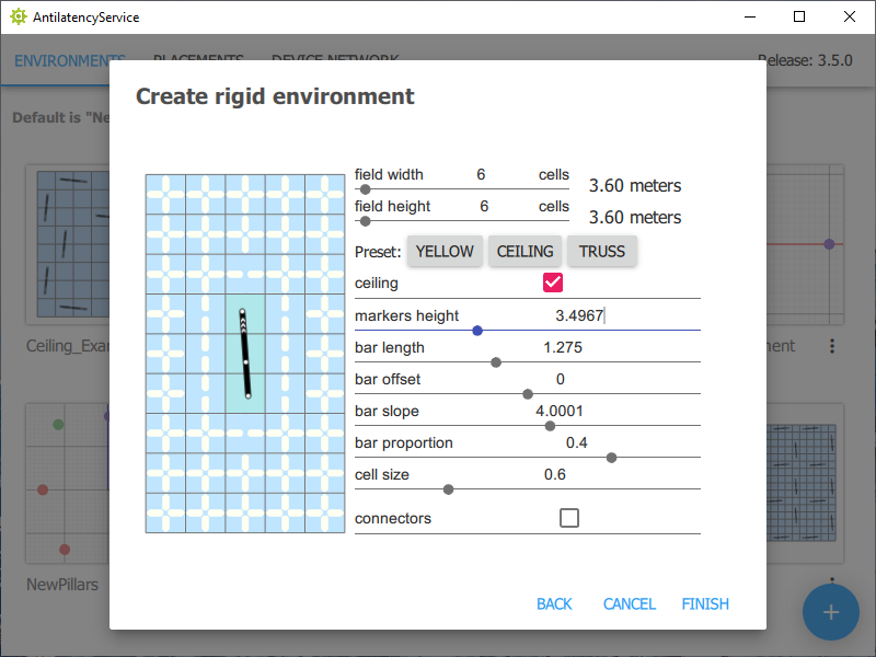
When creating the Environment it is necessary to take into account that the truss segment length is 2.5 m and the junctions length is 0.5 m. Thus, the step of the structure is 3.0 m.
The Environment is viewed from above.
An Environment might look like this (for a setup with a 6.5 x 6.5 m structure, truss placement, and a marker height of 3.565 m):

Note! When working with a truss tracking area, the installation of reference bars is only possible on truss segments, but not on junctions and not in the space between segments.
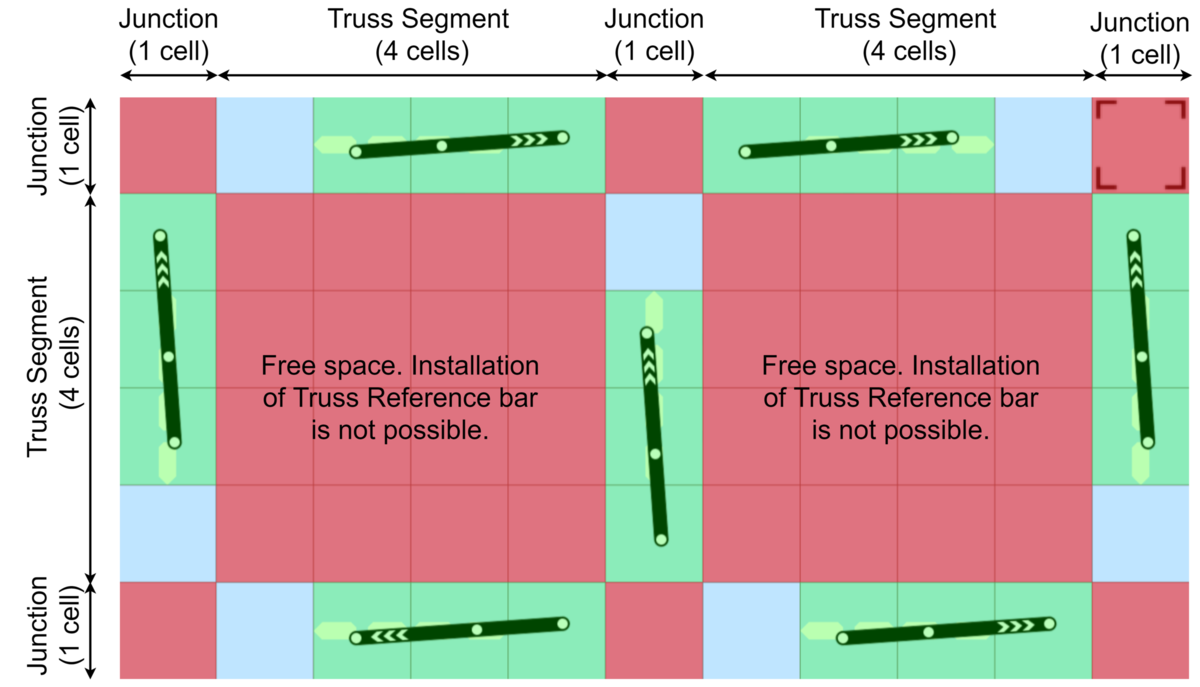
We recommend that you lock the unavailable cells in advance, as shown below. For more details, see the section: Locking cells in a HorizontalGrid Environment.
Assembling a truss tracking area
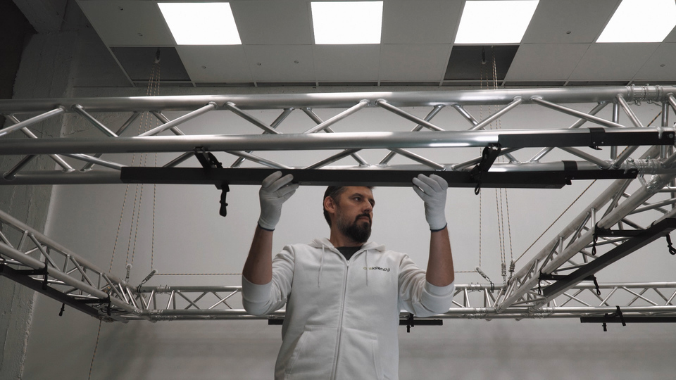
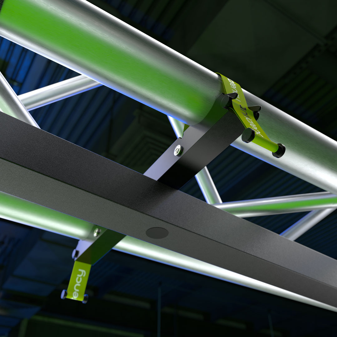
Truss Reference Bars are placed onto a pre-assembled truss structure (according to the Environment layout). Bracket mounts securely fix reference bars on truss segments.
The reference bars must be placed in strictly horizontal position. Any deviation from this position will negatively affect the tracking quality! Therefore, we do not recommend to install additional equipment on the same trusses where the tracking area is located. This is allowed only in case of extreme necessity. Be sure to check the position of the reference bars after installing additional equipment!
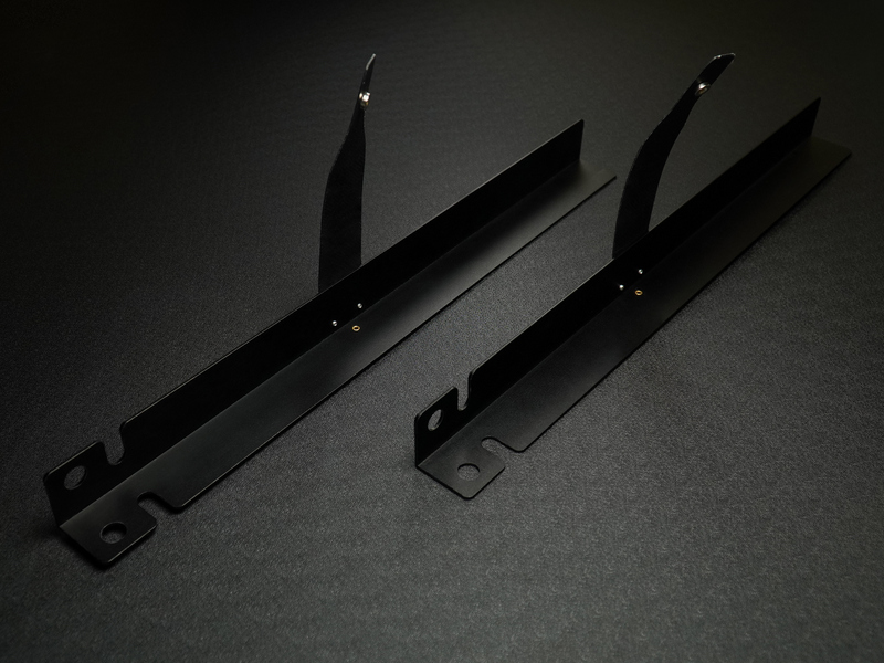
A special template should be used when positioning the reference bars (it's included in a kit). The template is put on the tapered connector closest to the edge of the segment with a hole and is fixed to the truss using a flexible fastener. A reference bar is installed close to it.
Thus, there are 4 possible placement options for each bar on the selected truss segment: with an offset from the beginning or end of the truss segment and with two possible slope angles. In the diagram,
T is a template, TRB is a truss reference bar.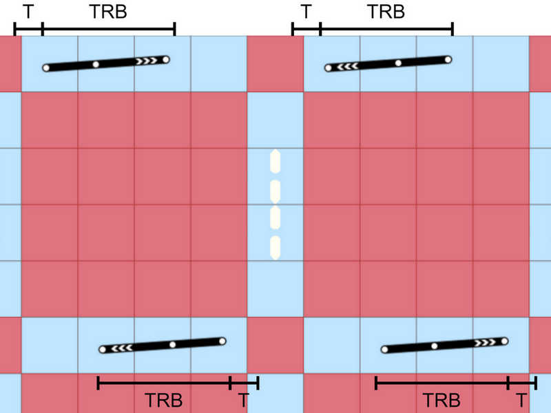
Truss Reference Bars Connection
Electrical switching is designed in a way that allows you to assemble a tracking area of any complexity without splitters. All wiring options can be implemented using cables included in the kit. Branching is done using paired connectors on Truss Reference Bars housings.
Power supply connection
It is recommended to use the following power supply to ensure the operation of the truss tracking area. The power supply is equipped with an AS-216-EN input connector with a switch and three KF2EDGWB-5.08 output connectors. In addition, the set to the power supply includes a H05VV-F 2x1.5 cable with an installed GX16 connector (female) for convenient connection of reference bars.
After installing the power supply, you can connect the tracking area. If everything is assembled correctly, then all indicators of the IR markers will light green. The truss tracking area is ready for use.