How to set up a ceiling tracking area
This section describes the assembly and installation process for a Ceiling tracking area.
Table of contents
The Antilatency ceiling tracking area consists of IR markers, which are located in accordance with the Environment. A sequence of three IR markers, located proportionally relative to each other, forms a Reference Bar. Each IR marker is securely fixed in the ceiling tile holes due to the aluminum housing.
Please note, that the installation of the Armstrong type suspended ceiling system is carried out by the client on their own. Before starting the tracking area placement, make sure that the ceiling grid is installed correctly (its strictly horizontal position, observance of the 90° angle between intersecting slats).
For ceiling tracking area setup you will need:
- an Environment in AntilatencyService;
- mounted grid of the suspended ceiling system;
- stranded copper wires 2x1.00 mm² (17 AWG);
- electric wire ferrules E1008 in two different colors for easy mounting;
- power supply unit with an output voltage of 18 V.
The output current is calculated using the formulaN × 0.1 A, where N is the number of IR markers; - standard cable for connecting power supply unit to a 220 V mains.
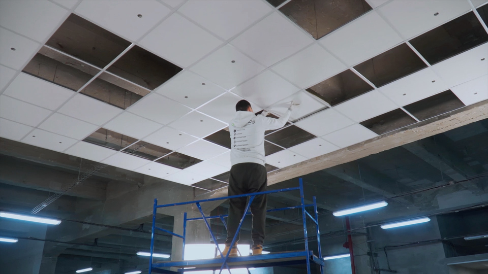
The ceiling tracking area installation process is shown in details in our video.
Сonfiguring the ceiling Environment in AntilatencyService
You can use the AntilatencyService to create a HorizontalGrid Environment layout from scratch or edit a previously saved version (see Environment examples for ceiling tracking areas).
Load the "Ceiling" preset. Check the
ceiling checkbox and set the correct markers height.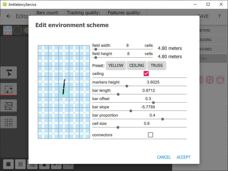
Please, read here to learn more about the HorizontalGrid Environment: How to create a HorizontalGrid Environment for your tracking area
In AntilatencyService the standard step is 0.6 m. If for some reason you cannot use the 0.6 m step, then the reference bar size should be recalculated. To obtain the correct parameters for your tracking area, you can contact the Antilatency support service. Read more about configuring the Environment in the editor: Environment editor.
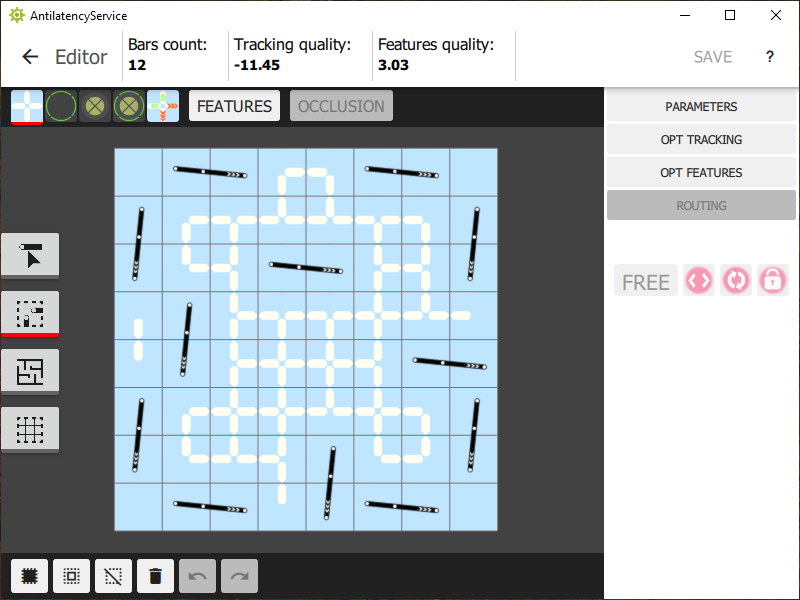
The Environment with a 4.8 x 4.8 m structure might look as follows:
The Environment is viewed from above.
Ceiling tiles preparation
First of all, you need to open the holes in the ceiling system tiles. To do this, you can use a screwdriver with a core drill of the 40,2 mm outer diameter, or a laser cutting CNC machine. We recommend that you work strictly according to the drawings we have developed. The accuracy of hole-cutting and installation of ceiling tiles directly affects the tracking quality.
This drawing is designed for systems with a step of 0.6 m.
Use the Environment's layout grid to count the number of tiles with opened holes. For each reference bar you will need 1 tile with one hole and 1 tile with two holes. For example, the tracking area shown above consists of 12 reference bars. Respectively, for its assembly you need 12 tiles of each type.
Next, you need to place tiles with opened holes on the ceiling grid, according to the Environment.
Preparation and installation of IR markers
To assemble each reference bar, we need 3 IR markers and 2 pieces of cable 400 mm and 600 mm long. For convenience, it is recommended to crimp the wires ends different color ferrules.
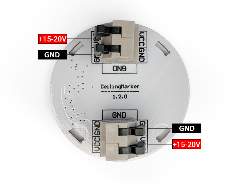
Strictly observe the polarity of the IR marker connection to avoid damage! It is forbidden to connect or disconnect IR markers while the power supply is running!
Power wires are connected to the IR marker according to the following scheme:
If the reference bars are assembled correctly, you can install them into the prepared holes of the ceiling tiles. We remind you that the AntilatencyService editor displays a top view of the area.
IR markers connection
The installed reference bars are connected in series with each other and wired to the power supply. If the circuit is assembled correctly, then the all IR markers indicators will light green.
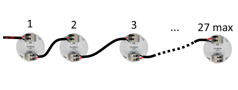
It is recommended to connect no more than 27 IR markers (9 reference bars) into one circuit. If you need to connect 30 IR markers or more (≥10 bars), then you should assemble several circuits. In this case, all circuits can be connected to one power supply unit, if its specifications allow it.
After wiring the IR markers to the power supply, be sure to measure the voltage drop in the circuit (voltage difference between the first marker input and the last marker output). The voltage drop for a 27 IR markers circuit should be less than 2-2.5 V. If the voltage drop exceeds 2.5 V, check the wires connection quality.
We recommend to re-check the compliance of the reference bars position to the prepared Environment.
After completing the check, you can install the remaining tiles. The ceiling tracking area is ready to use.