How to use Antilatency with EZtrack for virtual production
This tutorial aims to explain how to connect the Antilatency tracking system to EZtrack to create a live augmented reality for a virtual production.
To connect Antilatency to EZtrack, do the following:
Attach Antilatency tracker to the camera
We recommend attaching an Antilatency tracker to a dual rod clamp. You can find this kind of accessory at any grip kit reseller. Then centre the socket with tracker on the clamp and clamp it in place.
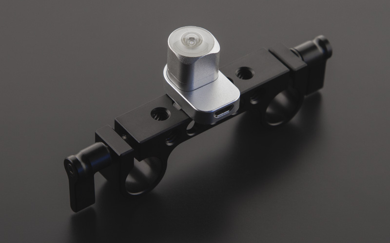
An Alt tracker attached to a dual rod clamp
Once you have connected the Alt to the clamp you can attach it to your camera body, just under the lens for instance. This Placement is perfect for a floor-based tracking area. For a ceiling-based tracking area, it is better to place the tracker above the camera. To learn more about the placement follow this link.
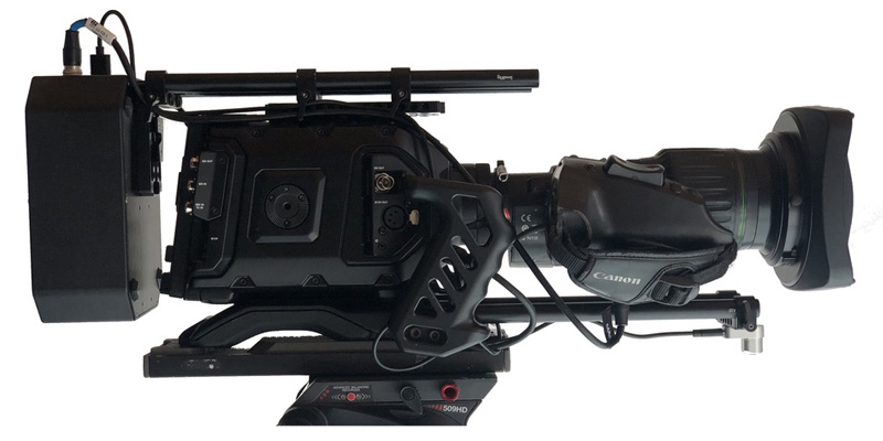
An Alt on a camera
Connect Antilatency tracker to EZtrack hub
You can then connect the Alt to the EZtrack core unit via USB.
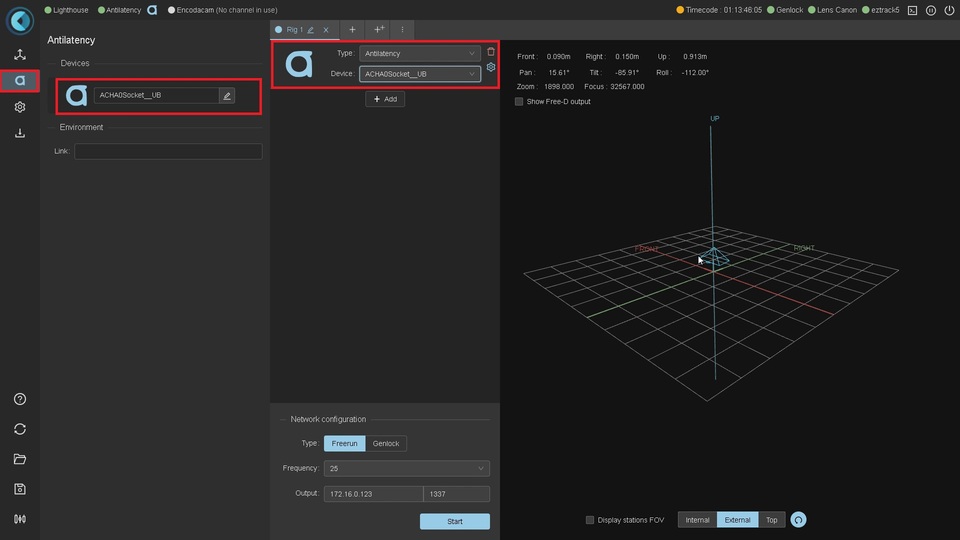
When the Alt is connected to the EZtrack core unit you will see the tracker appear on the Antilatency menu in the EZtrack web app. After this, you can add the tracker to a rig. To create a new rig, add an Antilatency node and select the tracker.
Set the offset between Alt and Camera sensor
The 3D position given by the Antilatency system is the position of your tracker. To perform augmented reality you need to feed the 3d position of the camera to the 3D render engine. So you have to offset the Alt tracker’s position to the camera sensor’s position.
Environment reference point (pivot point)
By default, EZtrack uses the DevKit environment. Here is a reference point scheme for the DevKit environment. In the environment editor the top of the image refers to the forward direction. The pivot point is in the middle of the image. You will get tracking coordinates relative to this reference.
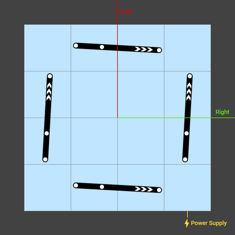
You can also load your custom environment by copying a new link in the web app tab. You can learn more about environments here.
Alt Tracker reference point (pivot point)
Here is the scheme for the tracker's reference point. Depending how you place your Alt tracker relative to the camera you have to align your tracker’s pivot point with the camera's optical center.
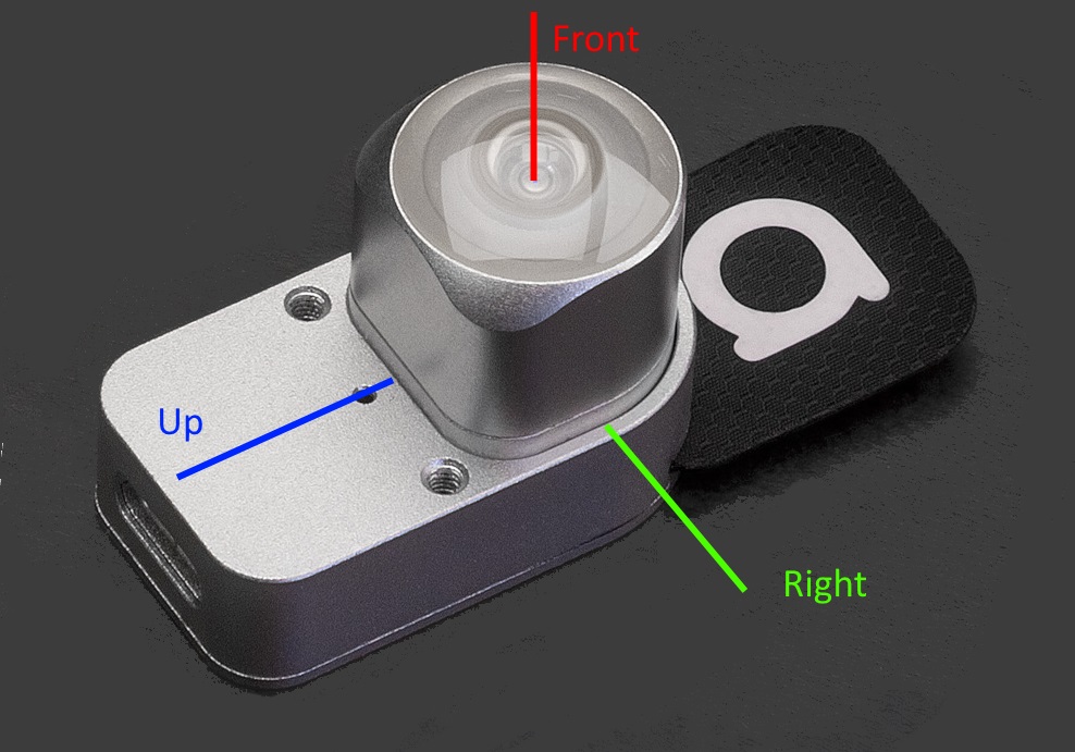
Alt tracker reference point
For instance with our current setup we add 4 nodes to match the sensor’s plane.
- tilt node: +90°
- pan node: +180°
- front node: -0.3m
- up node: +0.1m
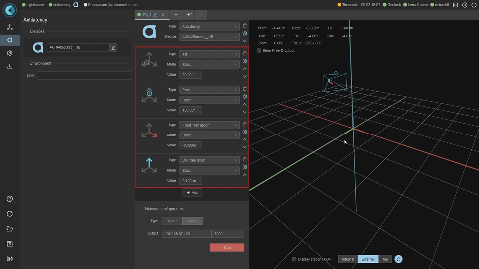
EZtrack offsets nodes to match the camera’s optical center
The first 2 nodes are for aligning both the Alt tracker and the camera’s optical center. The last 2 nodes are for offsetting to the sensor’s position.
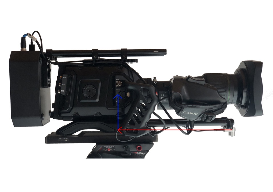
Offset to match the camera’s sensor
Conventionally, when doing virtual production, we offset the sensor to the plane of the camera. The nodal offset is added later in the lens file on the render engine side.
It is important to note that you can also set this offset directly using the Antilatency placements tool. However the bridge with the EZtrack interface has not been created yet. It will be available in the near future.
Get lens data from EZtrack
There are 2 ways to get lens data from EZtrack. One way is to connect a dedicated cable from the EZtrack core unit to your broadcast lens (Angenieux, Canon, Fujinon). The other way is to use external mechanical encoders for lenses without an embedded drive.
Select the right lens protocol in the dedicated EZtrack menu. Automatically it will add the zoom and focus data to your rig.
Connect tracking data to your render engine
EZtrack outputs information via the FreeD tracking data protocol over UDP. This is a very common camera tracking protocol used for broadcasts. All the main virtual production engines have FreeD input capabilities (ZeroDensity, Vizrt, Disguise...).
To set up data streaming simply set the IP address of the render engine and the PORT number to send it to.
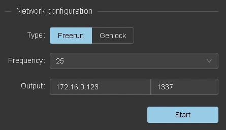
Output FreeD data