Configuring the Arbitrary2D Environment in AntilatencyService

The Environment of Arbitrary2D Environment is configured after the IR markers are physically placed on the working plane. Use the Environments tab in the AntilatencyService app to create or edit an Environment.
Configuration steps
- Place markers on the working plane.
- Create an Environment, the layout of IR markers in AntilatencyService.
- Place markers in the Environment as they are approximately located in the room.
- Align IR markers placement in the Environment by setting constraints and optimization.
- Calibrate the Environment.
IR Markers physical placement
It is assumed that the IR markers are already physically placed in the room and they are strictly in the same horizontal plane.
Try to keep a balance between the asymmetry and evenness of the marker distribution. This affects the main parameters of the Environment, you can read more about it in the Environment article.
Creating an Arbitrary2D Environment in AntilatencyService
To create a new Environment in the AntilatencyService app, click on the
+ button in the lower right corner and select the New environmentmenu item. Then select the Arbitrary2D type and specify an Environment name.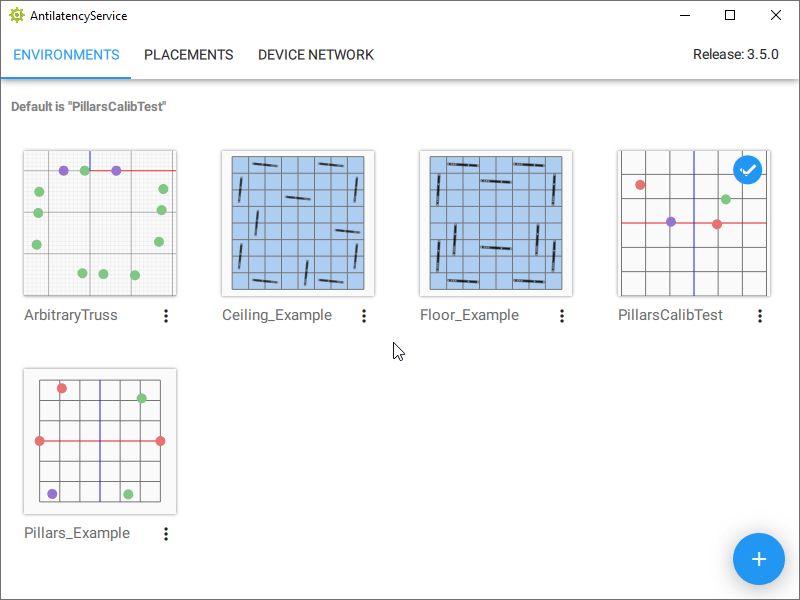
Then you should configure the Environment parameters:
- choose the type of marker placement –
Floor(IR markers are located under the tracked objects) orCeiling(IR markers are located above the tracked objects); - set the distance between the floor and the marker plane –
Markers height(use positive values if the markers are above the floor).

By default, the camera in AntilatencyService looks at the layout from above, as if at a room plan. There are usually no difficulties in transferring the location of the markers on the floor into the Environment, but you should watch out for the default camera view when copying a ceiling placement.
Controls in AntilatencyService:
- use the mouse scroll wheel to zoom the Environment in/out;
- click and hold the middle mouse button to move the visible part of the Environment;
- hold the right mouse button to change the tilt angle (camera movement);
- double-click the right mouse button to return to the default view.
If you are looking at the ceiling placement of markers from below, you can move the camera under the plane to check them on the layout in AntilatencyService. To do this, click and hold the right mouse button and move the plane as shown in the animation:
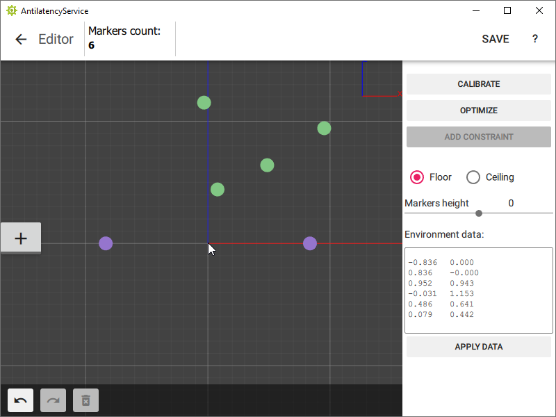
Placing the IR markers in the editor
The origin of the coordinate system is located between the first two markers. The step of the coordinate grid is 1 meter. These markers move synchronously along the X-axis only. They can be used to set the center or the edge of the Environmentг.
Next, add the remaining IR markers. The order is not important, but try to keep their approximate relative position. There are two ways to add markers and change their position:
- in the visualization window using the
+button and mouse movement; - in the
Environment datatext block by entering marker positions in X and Z coordinates.
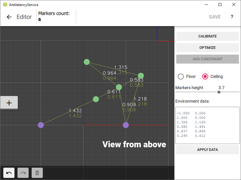
The top two rows in the
Environment data text block are the coordinates of the first pair of markers. The rest are the green markers in random order. After making adjustments, click on the Apply Data button.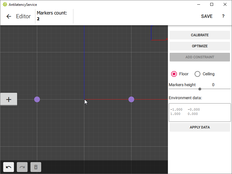
Setting constraints and optimization
To align marker positions in the editor to their physical positions, optimize the Environment. In order to do this, use the
Constraints tool for marker pairs.To create a
Constraint, follow these steps:- Measure the physical distance between 2 adjacent IR markers placed in the room. You may do so by using a regular or a laser measuring tape. The measurements should be made in the centers of the markers.
- Select these markers in the editor window (using the mouse area selection or the
Shift + left mouse buttonshortcut).
In the Android version of AntilatencyService, press theCtrlbutton, and then tap the required markers.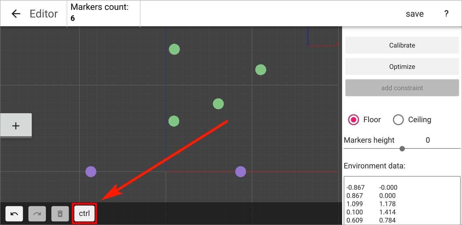
- Press the
ADD CONSTRAINTmenu button (or theCtrl + Qkeyboard shortcut). - Set the measured distance between the centers of these markers in meters (ex.
1.275).
An arrow with dimensions between the markers will appear. The upper number is the measured distance between the markers, and the lower number is the distance on the layout.
- If the distance in the Environment is less than the measured distance, then the line and number will be red.
- If the difference between the distances is within acceptable limits, then the line and number will be green.
- If the distance between the markers is greater than the measured one, then the color will be blue.
Repeat the process for the remaining pairs of IR markers. For optimization to be effective, the Constraints' lines must form a rigid shape. The more measurements there are, the better; we recommend at least three for each marker.
Measure the distances between the markers, which correspond to the different colored markers in the Environment as accurately as possible!
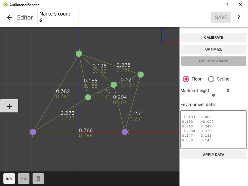
After you have made all the measurements and added them to the Constraints in the Environment, click
OPTIMIZE to automatically correct the position. Make sure that all the Constraint lines have turned green.Remember to save the Environment changes (the
SAVE button in the upper right corner).Calibrating Environment
Calibration can’t be used instead of optimization! It corrects the position of the IR markers in the Environment only if they slightly deviate from their actual location.
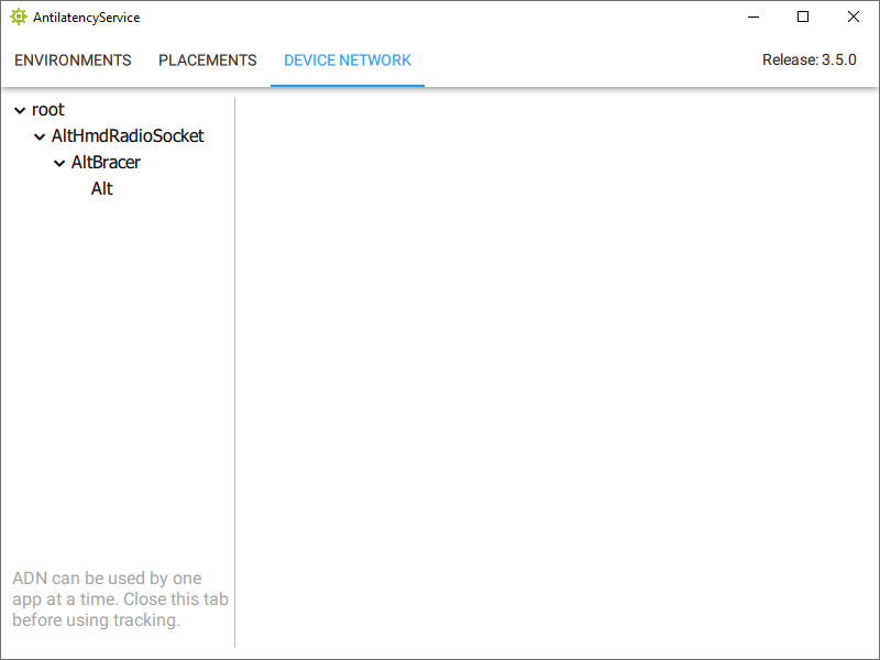
To perform an Environment calibration you will need: an Alt, a Universal Radio Socket and a Tag or a Bracer.
- Click the
DEVICE NETWORKtab in AntilatencyService. - Turn on the devices, check they are displayed in the device tree. If they don't appear, use the instructions: How to configure Antilatency wireless devices.
- Go back to the
ENVIRONMENTStab, select your Environment, click Edit. - Click the
CALIBRATEbutton.
Next, take a Tag or a Bracer with an Alt and prepare to walk around the tracking area while calibrating. You must move the socket so that the Alt sees the tracking area from as many angles as possible (different positions and rotations).
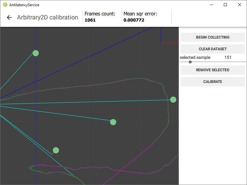
- Press the
BEGIN COLLECTINGbutton. - Turn on the socket with an Alt, walk around the tracking area until you get about a 1000 frames (
Frames countfield). - Press the
STOP COLLECTINGbutton. - Use the
selected samplefield to select positions that look like tracking errors (incorrect peak points in the tracker path) and delete them (REMOVE SELECTEDbutton).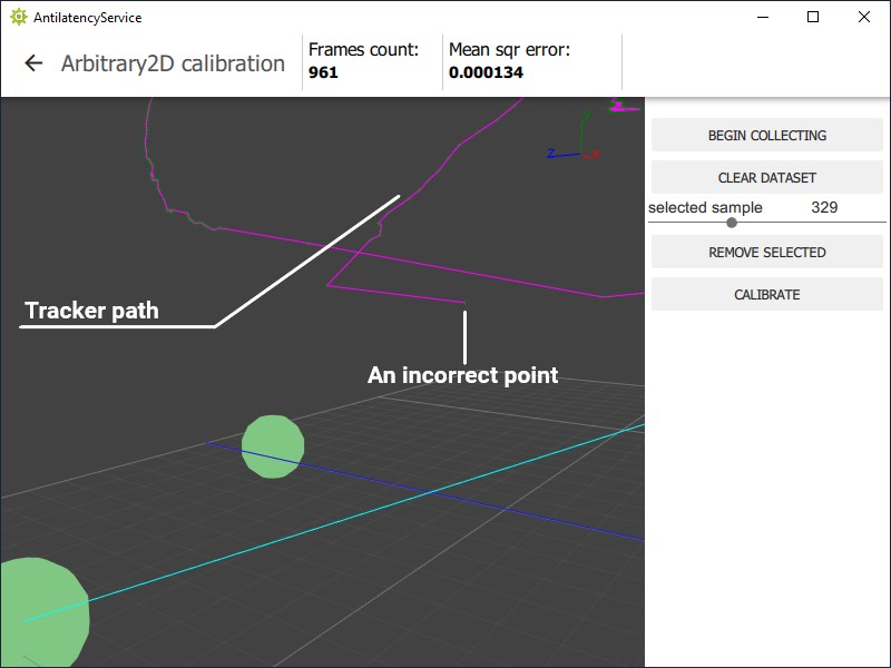
- Now pay attention to the
Mean sqr errorfield. Press theCALIBRATEbutton and then the value ofMean sqr errorshould decrease at least by an order of magnitude, and preferably to0. - If the
Mean sqr erroris still greater than0, pressCLEAR DATASETand repeat the calibration algorithm.
You can see how accurately the beams from the Alt tracker hit the markers by moving the slider along the
selected sample line. If no beam hits a marker, then the distances between this and other markers should be measured again.If no tracking data has been captured during calibration, try to measure the distances between markers more accurately or inspect the Environment for features. If the measurements were carried out with a lot of errors, the Alt tracker will not be able to match the layout and the actual location of the markers.
The calibration is successful if most of the beams enter the markers accurately and without deviations when approaching, and the
Mean sqr error value has significantly decreased or is equal to 0. After successful calibration, click the back arrow and the APPLY button in the pop-up window. Then save the changes (SAVE button).Now the Arbitrary2D Environment corresponds to the actual location of the IR markers in the room. The configuration of this Environment is completed.
Remember to set your Environment as a default one. You can see the instructions in Environments.